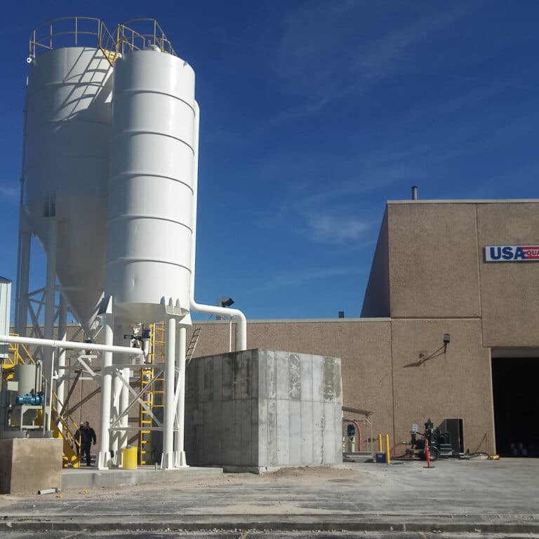
A plant running below its dewatering target faces a choice: expand filter capacity, or find out whether the filter is even the constraint. That decision shapes everything that follows in a retrofit, including what gets surveyed, what gets tied in during the shutdown, and what the commissioning test is actually meant to prove.
Existing Plant Baseline and the Real Bottleneck
| Baseline area | Question the current plant must answer | Retrofit decision it protects |
|---|---|---|
| Solids and water balance | What is the current solids and water balance before the retrofit is defined? | Establishes the baseline for locating the real constraint and sizing the integrated duty. |
| Feed variability | Could changing feed conditions be driving changes in dewatering output? | Shows whether temporary or pilot testing is needed before fixing the equipment route, media, or surge capacity. |
| Thickening | Could thickening be the constraint behind low filter output? | Prevents a thickening constraint from being treated as a filter-only sizing problem. |
| Pumping | Could pumping be limiting the duty delivered to the dewatering step? | Keeps the pump interface within the retrofit scope when it contributes to the bottleneck. |
| Controls | Could control behavior be limiting integrated output? | Keeps the control interface within the retrofit scope when it contributes to the bottleneck. |
| Cake removal | Could cake removal be constraining filter output? | Keeps the discharge path and cake-handling interface within the retrofit scope when they contribute to the bottleneck. |
A retrofit scoped before the baseline is understood tends to buy capacity in the wrong place. Low filter output looks like a filtration problem from the operator’s chair, because that is where the shortfall becomes visible. But the constraint producing that shortfall can sit upstream of the filter, downstream of it, or inside the control logic that governs how the whole sequence runs.
Establishing the current solids and water balance is the starting point because it fixes what the retrofit is actually solving. Without it, a buyer risks sizing new filtration equipment against a demand figure that reflects a thickening limitation, a pumping limitation, or a cake-handling limitation rather than the filter’s own capability. If thickened underflow arrives thinner or more variable than the filter was designed around, the filter cycles longer or produces wetter cake, and the output shortfall gets attributed to filtration when the corrective action belongs to the thickener. If the pump delivering feed to the filter cannot sustain the pressure or flow the filtration step needs, the filter’s rated throughput is never actually tested — it is starved. If the control system does not sequence fill, pressing, and discharge efficiently, cycle time grows and apparent capacity falls, even though every mechanical component would pass on its own.
Cake removal sits at the other end of the same problem. A filter that performs correctly on the pressing side but is constrained by how discharged solids move away from the press will still read as underperforming to anyone measuring total output per shift. Where a retrofit addresses the filter but leaves the cake-discharge path unchanged, the plant can realize some of the new capacity and still miss the overall target, because the limiting step moved rather than disappeared.
This is the judgment the baseline work protects: before fixing equipment geometry, filter area, or media, the buyer needs to know which step in the sequence — thickening, pumping, control, filtration, or discharge — is actually setting the ceiling. That determination changes the retrofit scope itself. A project that turns out to be a thickening or pumping constraint calls for different equipment and different tie-in points than one that is genuinely filtration-limited, even though both can present as “the filter press isn’t keeping up.”
Mass Balance and Feed Variability Before Retrofit Sizing
The baseline balance answers what the plant is producing today. It does not answer whether that feed will stay the same after the retrofit is in service, and that second question changes how conservatively the new equipment should be sized.
Feed variability matters because dewatering equipment is selected against an assumed feed condition — solids concentration, particle-size distribution, and flow rate — and a retrofit designed around a single averaged value can be wrong in either direction. Where feed solids content swings with ore type, process rate, or upstream reagent dosing, a filter sized for the average condition can be undersized during the periods when feed arrives thinner or at higher flow, and oversized or inefficient during the periods when it arrives more concentrated. The same variability affects whether surge capacity is needed ahead of the dewatering step, because a tank or buffer that absorbs feed swings changes the duty the filter itself has to handle.
This is the condition under which temporary or pilot testing earns its place in the retrofit plan. Where the existing plant’s feed behavior is already well characterized and stable, sizing from the established baseline carries less uncertainty, and the retrofit can proceed on that basis. Where feed conditions are expected to shift — because of an ore change, a process modification elsewhere in the plant, or simply because the existing baseline data does not cover the full range of conditions the plant actually sees — testing on a representative feed sample, using a pilot-scale or temporary unit, gives the buyer data before the equipment route, filter media, or surge sizing is fixed rather than after.
The decision this protects is not just equipment sizing. It also governs media selection, because different filter media respond differently to changes in particle size and solids loading, and a media choice optimized for one feed condition may need retesting against the project’s realistic range. A buyer who skips this step because the baseline looked sufficient is accepting that the retrofit’s sizing basis holds across whatever feed variation the plant actually produces — a decision that the testing step exists to confirm rather than assume.
Space, Structure, Utilities, and Access Constraints
Once the bottleneck and the feed basis are understood, the retrofit still has to fit inside a building that was not designed around it. Existing plants constrain equipment choice in ways a greenfield design does not, and surveying those constraints before fixing equipment geometry avoids a design that is correct on paper and unbuildable on site.
Floor loading is one such constraint: dewatering equipment, especially filtration equipment holding a full charge of slurry or cake, imposes a distributed and point load that the existing structure may or may not have been designed to carry at that location. Where the structure cannot support the preferred equipment footprint in its preferred location, the retrofit has to either relocate the equipment, modify the structure, or select equipment with a different loading profile — each of which carries different implications for the rest of the layout.
Access governs whether the chosen equipment can physically enter the building and reach its installation point, and whether it can later be removed for major maintenance or replacement. A filter press or disk filter that fits the available footprint may still be undeliverable through the existing doorways, crane coverage, or laydown area, which means access has to be checked against the specific equipment route being considered, not just against the general category of equipment.
Drainage and utilities determine whether the retrofit can tie into existing services or requires new runs. Filtrate and wash water need a drainage path with adequate capacity and the correct slope; compressed air, electrical supply, and any other utility the equipment requires need existing capacity confirmed, not assumed. Pipe routing between the retrofit equipment and the rest of the process — feed lines, filtrate lines, any recycle or wash-water return — has to be checked against what is physically available in the existing plant, including where those routes cross other equipment, structures, or walkways.
Controls integration is part of the same survey: whether the existing control system has spare capacity to integrate a new equipment package, or whether the retrofit requires its own control skid interfaced back to the plant. And the cake-discharge path — where cake goes once it leaves the equipment, and what conveys it there — has to be surveyed alongside the equipment itself, because a discharge path that cannot handle the new equipment’s output reintroduces the same bottleneck the retrofit was meant to remove.
Thickener, Pump, Control, and Cake-Handling Tie-Ins
The baseline work identifies which of these interfaces matters for a given project; this stage is where that interface gets designed and connected. A retrofit’s scope is not limited to the new filtration unit — it includes every point where that unit has to exchange material, signal, or service with equipment the plant already operates.
The thickener tie-in matters most directly where the baseline work found the thickener contributing to the constraint. If underflow density or consistency needs to improve before the new filtration equipment can perform to its design basis, the retrofit scope has to include whatever change makes that underflow consistent — which changes the project from a filtration-only retrofit to one that touches the thickening step as well. Where the thickener is already delivering adequate and consistent underflow, the tie-in is simpler: matching flow and pressure at the interface without changing the thickener’s own operation.
Pump tie-ins carry a similar branch. A pump that was sized for the previous equipment’s duty may not deliver the flow or pressure the new filtration equipment requires, particularly where the retrofit increases filter area or changes cycle time. Confirming pump duty against the new equipment’s actual requirement — not just against the old duty point — avoids installing new filtration capacity that the existing pump cannot feed.
Control integration determines how the new equipment’s sequencing coordinates with the plant’s existing automation. Where the retrofit equipment runs its own control package, the tie-in question is how that package communicates with the plant control system — what signals pass in each direction, and how an upset on either side is handled. This is a design and communication detail distinct from the formal verification of the finished interface, which belongs to the acceptance-testing stage.
Cake-handling tie-ins connect the new equipment’s discharge to the plant’s existing conveyance — conveyors, bins, trucking, or further processing. Where the new equipment’s cake production rate or cake character differs from what the existing handling system was designed around, that handling system itself may need modification, which again expands the retrofit’s scope beyond the filtration unit alone.
How a project’s own configuration and site information get used to work through these interfaces is part of what a supplier’s quotation review is meant to cover — the specifics of each tie-in depend on the equipment route chosen and the site conditions already surveyed, which is why that information needs to be supplied accurately rather than assumed.
Shutdown and Commissioning Sequence
| Stage | Work completed at this stage | Gate before proceeding |
|---|---|---|
| 1. Define the baseline | Establish the current solids and water balance and identify the real bottleneck. | Keep retrofit sizing open while the baseline could change the required duty. |
| 2. Survey the installation | Check access, floor loading, drainage, utilities, pipe routes, controls, and the cake-discharge path. | Do not fix equipment geometry or tie-ins until these site constraints are known. |
| 3. Reduce feed uncertainty | Use temporary or pilot testing where feed uncertainty could change the equipment route, media, or surge capacity. | Fix those choices only after the relevant uncertainty has been addressed. |
| 4. Complete shutdown tie-ins | Sequence the thickener, pump, control, and cake-handling tie-ins within the plant’s shutdown limits. | Complete the planned tie-ins before commissioning the integrated duty. |
| 5. Commission the integrated system | Commission the retrofit after the required tie-ins are complete. | Move to performance verification under the agreed feed and test conditions. |
| 6. Verify the duty | Verify integrated duty using the project-specific acceptance scope and checklist. | Judge the result only against the agreed feed conditions, test conditions, and separately defined duty measures. |
All of the preceding decisions converge on a constraint that an operating plant imposes and a greenfield project does not: a shutdown window with a defined limit. The sequence in which work gets done is not a scheduling preference — it is what allows a retrofit to be installed without the preparatory work consuming the shutdown itself.
Baseline definition and the site survey belong before the shutdown, not during it, because both inform decisions — equipment geometry, tie-in points, feed-related sizing — that need to be settled before shutdown work starts. A shutdown spent discovering that the floor cannot carry the planned equipment, or that feed variability changes the required surge capacity, is a shutdown spent on decisions that should have already been closed.
Feed-uncertainty testing belongs in the same pre-shutdown category where it is needed at all. Pilot or temporary testing takes its own time and is only useful if its result is available before the equipment route, media, and surge capacity are fixed — which means it has to run far enough ahead of the shutdown that its findings can still change the plan.
The shutdown itself is reserved for what cannot happen while the plant runs: the physical tie-ins to the thickener, pump, control system, and cake-handling path. Sequencing those tie-ins against the shutdown’s duration means knowing, before the shutdown starts, which tie-ins are required, in what order they depend on each other, and what happens if one tie-in takes longer than planned.
Commissioning follows the tie-ins, and duty verification follows commissioning — not because that order is more convenient, but because verifying integrated duty before every required tie-in is complete produces a result that does not reflect the finished system. The verification itself needs its own agreed basis, which is what the acceptance stage establishes.
Integrated Acceptance Under Agreed Feed Conditions
| Acceptance item | Project-specific agreement needed | What the result can establish |
|---|---|---|
| Test scope and activities | The factory, site, or integration activities included in the acceptance scope | Identifies which system checks are included; it does not by itself establish dewatering duty or cake or filtrate performance. |
| Responsibilities and checklist | Agreed responsibilities and a project-specific checklist | Establishes how the agreed acceptance activities are assigned and checked. |
| Feed basis | The feed conditions used for the integrated-duty test | Limits the duty conclusion to the agreed feed conditions. |
| Integrated-duty test | The duty to verify and the agreed test conditions | Establishes integrated duty only under those agreed test conditions. |
| Cake result | A separately agreed cake measure and test | Supports only the project-specific cake conclusion; it is not a universal moisture guarantee. |
| Filtrate result | A separately agreed filtrate measure and test | Supports only the project-specific filtrate conclusion; the reference does not supply a universal performance result. |
A retrofit’s commissioning can be mechanically complete without the plant having confirmed that the system does what the project required. That confirmation needs its own agreement, made explicit before the test runs rather than inferred afterward from whatever result the test happens to produce.
IEC 62381, the Factory Acceptance Test / Site Acceptance Test / Site Integration Test standard, establishes that acceptance testing works from an agreed scope — which activities are included, who is responsible for each, and what checklist the test follows. That framework is built for automation-system context, which means it supports agreement on test scope and responsibility; it does not itself define what duty, cake, or filtrate measures should be tested, or what results would count as acceptable. Those measures need their own project-specific definition.
Feed basis is the condition that bounds every result that follows. A duty figure confirmed under one feed condition does not transfer to a different feed condition, which is the same variability the project addressed earlier when deciding whether pilot testing was needed before sizing. The acceptance test has to state which feed condition it used, because that statement is what gives the resulting duty figure its meaning.
Cake and filtrate results need separate agreement for the same reason. A cake-moisture or filtrate-clarity result produced under the project’s agreed test conditions establishes that result for this installation under those conditions — it does not transfer as a general performance claim, and general technical references do not substitute for a project-specific result. The EPA’s biosolids fact sheet on recessed-plate filter presses, for instance, documents the mechanical components, support structure, footprint, and operator interaction typical of installed pressure-filter systems, along with representative testing — but it describes municipal biosolids applications, and its figures do not transfer to a tailings duty without separate, project-specific confirmation. Likewise, a manufacturer’s process overview, such as Metso’s description of a dry tailings plant covering thickening, pressure filtration, cake handling, and water recovery, establishes the identity and general scope of that kind of plant without constituting a moisture guarantee or a safety conclusion for any specific facility.
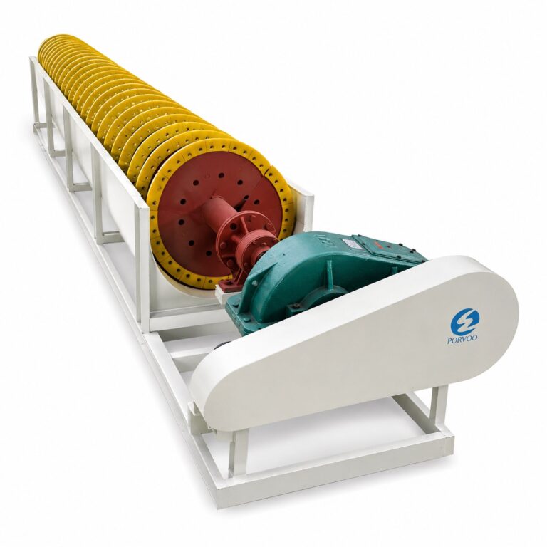
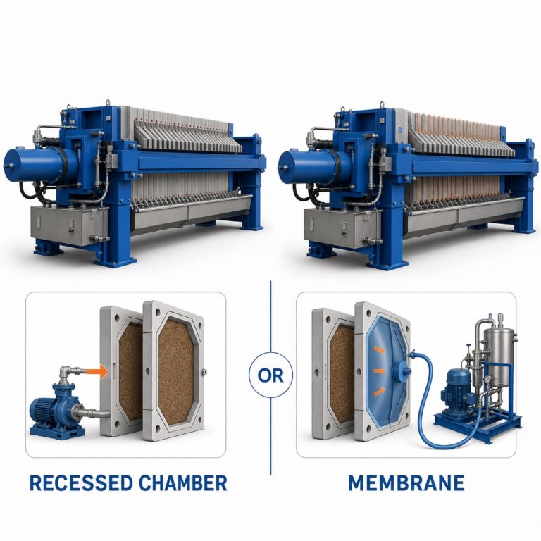
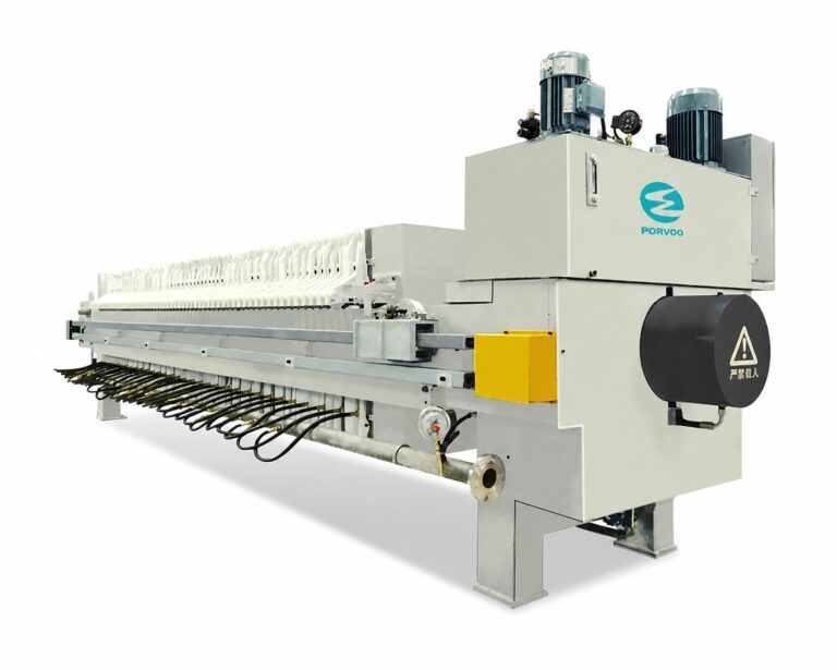
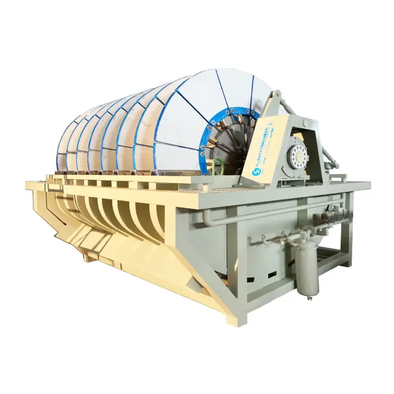
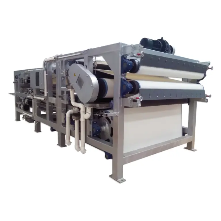
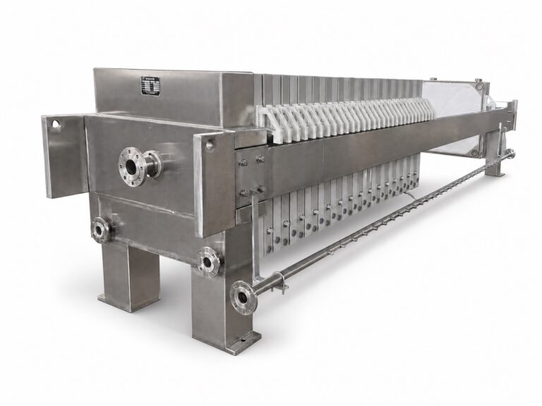
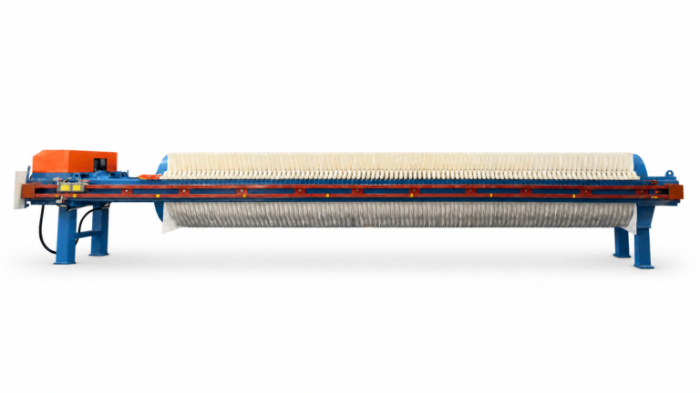
Where a buyer needs a conclusion about this project’s cake condition, filtrate quality, or integrated throughput, the path runs through an acceptance test agreed in advance — scope, feed condition, measurement method, and responsibility all stated — rather than through analogy to a different installation’s documented performance. Equipment such as a vacuum ceramic disk filter or a recessed chamber filter press can be matched to the retrofit’s duty requirement during configuration review, but confirming that the installed, tied-in system meets that duty under this plant’s feed remains a separate, later step.
Frequently Asked Questions
Q: How can we tell whether the filter itself should be the main retrofit target?
A: Start with the current solids and water balance, then check whether feed variability, thickening, pumping, controls, or cake removal is limiting output. Keep those interfaces in scope until the real bottleneck is identified, because a filter-only change may leave the plant constraint unresolved.
Q: When is temporary or pilot testing useful before selecting the dewatering route?
A: Use testing when uncertainty in the actual feed could change the equipment route, filter media, or required surge capacity. Define the feed conditions to be examined and use the results to close those choices before fixing the retrofit design.
Q: What site information should be ready before equipment geometry is fixed?
A: Document access, floor loading, drainage, utilities, pipe routes, control interfaces, and the full cake-discharge path. These checks reveal the physical and operating constraints that must shape equipment placement and tie-in planning.
Q: How should the retrofit be planned around a limited shutdown window?
A: Complete the baseline work, site survey, and any uncertainty-reduction testing before the shutdown, then sequence the thickener, pump, control, and cake-handling tie-ins within the available window. Commission the integrated system only after the planned tie-ins are complete, and reserve the agreed verification work for the commissioned system.
Q: What must an acceptance plan define before integrated-duty testing begins?
A: Agree on the included test activities, responsibilities, checklist, feed basis, duty to verify, and test conditions. Define separate measures and tests for any cake or filtrate conclusions, and limit acceptance findings to the agreed conditions rather than treating them as universal performance guarantees.