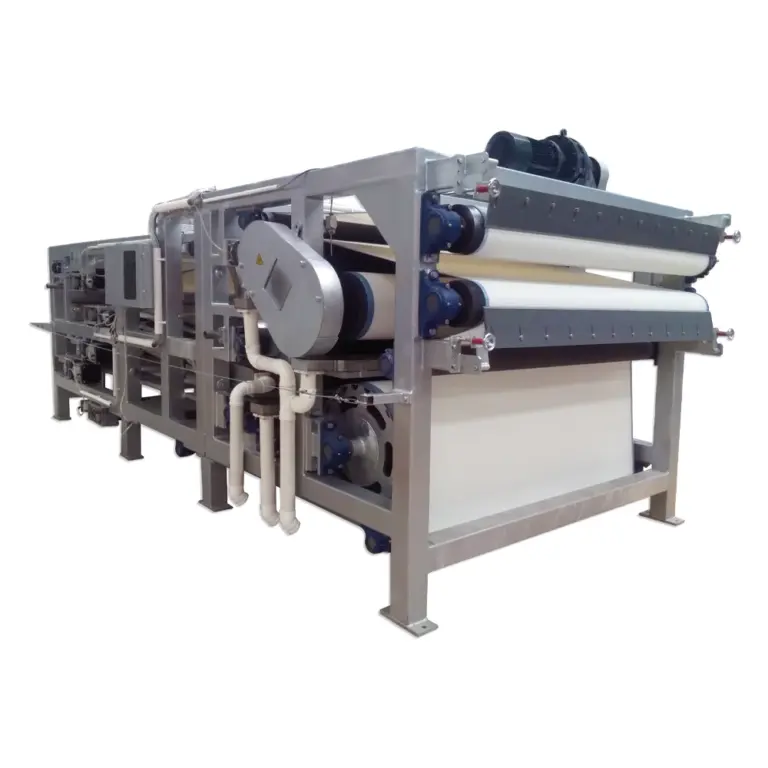
A single pressure-and-flow reading taken at one moment of chamber filling cannot tell a buyer what pump to specify. The filter press cycle changes the duty continuously as the chamber fills, and a pump selected against the wrong point in that cycle will be mismatched for the rest of it. The question a buyer needs answered before issuing an RFQ is not “what pressure and flow does the press need,” but “how does that pressure and flow change across the fill, and what does the pump have to do at each stage.”
Reading the Pressure-Flow Trace During Chamber Filling
| Trace view | What it shows | Decision boundary |
|---|---|---|
| Pressure across chamber filling | Pressure recorded through the fill sequence | One endpoint does not describe the changing duty |
| Flow across chamber filling | Flow recorded through the fill sequence | One endpoint does not describe the changing duty |
| Pressure and flow together | The duty seen as the chamber fills | Pump selection still requires slurry properties, circuit losses, control logic, and operating limits |
Chamber filling is not a single hydraulic condition. As slurry enters an empty chamber, resistance is low and flow can be high; as solids build against the filter media and the chamber approaches its working pressure, resistance rises and flow falls. A pump that is selected using only the final pressure reading, or only the initial flow reading, is being sized against one slice of a duty that moves continuously between those two points. The trace that matters is the full curve: pressure recorded throughout the fill sequence, read together with flow recorded throughout the same sequence.
This matters because pumps and filter presses do not share a single fixed operating point the way two pipes joined by a flange might. The press presents a changing resistance to the pump, and the pump’s own performance curve determines how it responds to that changing resistance. If the pump’s curve is steep across the relevant pressure range, flow may fall faster than the press cycle assumes as pressure builds, extending the portion of the cycle spent at low flow. If the curve is flatter, the pump may continue delivering flow into a chamber that is already approaching its working pressure, which changes how the fill stage interacts with the press’s own control logic for ending that stage.
A buyer who has only an endpoint pressure and an endpoint flow has two numbers that describe two different moments, not a duty. Those two numbers might even come from different parts of the cycle on different test runs, which makes them unsuitable for comparing pump curves against. What a pump supplier needs is the shape of the relationship across the fill, not a pair of extremes.
Where the trace shows a long period of gradually rising pressure at relatively stable flow, the pump duty is dominated by its mid-curve behavior and the selection should weight that region. Where the trace shows flow dropping sharply as pressure approaches its working value, the pump’s behavior at the top of its curve, and how it is controlled as it approaches that region, becomes the more relevant selection detail. Reading the trace this way, rather than extracting a single value from it, is what lets a pump curve be matched to the actual duty instead of to a convenient summary of it.
Slurry Properties That Change the Pump Duty
The pressure-flow trace describes what the press asked for during a specific test; it does not by itself explain why the pump had to work that way. The properties of the slurry being fed are what connect the trace to a pump selection that will hold for the project’s actual material, because a trace taken with one slurry does not transfer cleanly to a different one even if the press and cycle are otherwise similar.
Solids content changes the resistance the pump must push against and also changes how that resistance develops as the chamber fills; a higher solids content can mean the chamber reaches its working pressure sooner in the cycle, shifting more of the duty toward the pump’s high-pressure, low-flow region. Particle behavior matters separately from solids content alone: a slurry that settles, that is abrasive, or that tends toward particle breakdown under shear places different demands on the pump’s wetted path and internal clearances than solids content by itself would suggest. Viscosity or rheology observations describe how the slurry resists flow under the shear conditions the pump actually imposes, which is not the same as how it behaves at rest, and a slurry that appears straightforward in a sample container can behave differently once it is moving through an impeller or rotor at pumping speed.
Temperature affects viscosity and can affect conditioning chemistry if the slurry has been dosed before reaching the pump; a slurry’s conditioning state, whether it has been treated with flocculant or coagulant upstream, changes particle size and settling behavior in ways that alter both the pressure-flow trace and the pump’s exposure to abrasive or shear-sensitive material. A pump selected from a trace alone, without these properties stated alongside it, is being matched to a duty whose cause is not fully known, which leaves the supplier guessing at how the duty will shift if the project’s actual slurry differs from the one used to generate the trace.
Feed Pump Duty Versus the Press Hydraulic System
| System | Role in the filter-press package | Decision boundary |
|---|---|---|
| Slurry feed pump | Acts as the process interface for feeding slurry during chamber filling | Use the slurry-feed pressure and flow trace together with slurry, circuit, control, and operating-limit inputs |
| Press hydraulic system | Closes the filter press | Do not treat slurry-feed pump duty as the press-closing hydraulic duty |
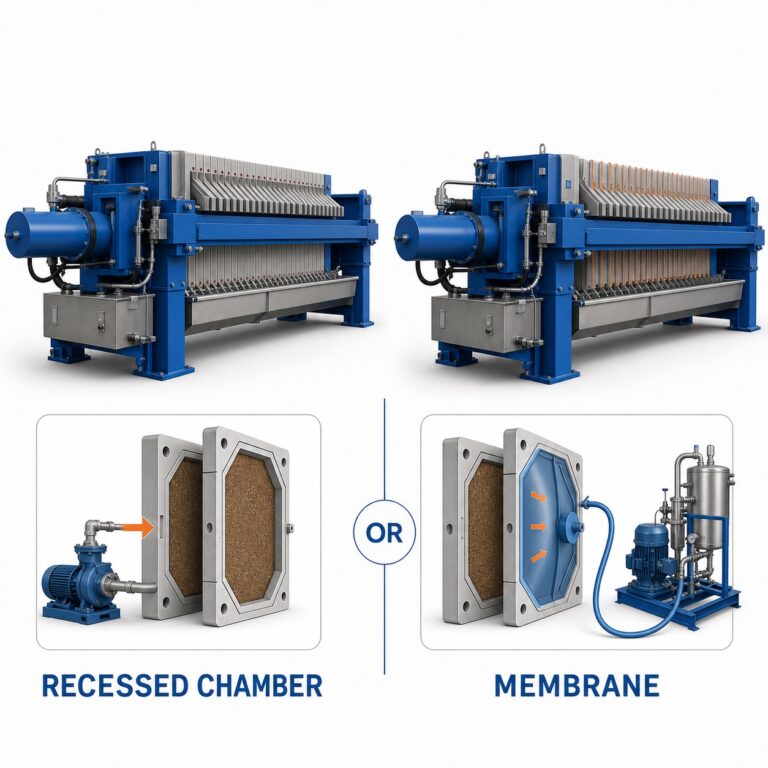
A filter press package contains two pressure systems that are easy to conflate because they operate on the same machine at overlapping times, but they are not the same duty and do not get selected against the same criteria. The slurry feed pump moves slurry into the chamber during filling; the press’s hydraulic system closes and holds the plates under pressure so that filtration can occur at all. One is a process interface handling the material being treated; the other is a mechanical clamping function handling hydraulic fluid.
Treating the feed pump’s pressure as if it were the same quantity as the press-closing pressure leads to selecting against the wrong reference point. The feed pump’s duty is set by the resistance the slurry encounters as it fills a chamber that is already closed; the hydraulic system’s duty is set by the clamping force needed to keep the plates sealed against that same internal pressure plus whatever margin the press design specifies. These two pressures can be numerically related in a given press design, but they are generated by different systems, respond to different inputs, and fail in different ways if misapplied.
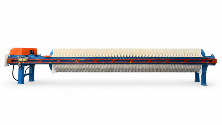
Where a buyer requests a feed pump quotation, the information the pump supplier needs is the slurry-side pressure and flow trace together with the slurry properties and circuit conditions, not the hydraulic clamping specification. Where a buyer requests the press itself, the hydraulic system is specified as part of the press package rather than against the feed pump’s duty. Confusing the two during an RFQ can result in a pump selected against a pressure it will never see, or a hydraulic question being asked of a pump supplier who has no basis to answer it. Keeping the two systems distinct in the request is what allows each supplier to size against the duty that is actually theirs. The filter press itself, including how its hydraulic closing system is integrated into the overall package, is a separate specification question from how the slurry is fed to it.
Circuit Losses and Control Logic Outside the Test Press
A pressure-flow trace generated on a test press describes the press’s own resistance, not the resistance the pump will see once it is installed in the project’s actual piping circuit. Pipe length, fittings, elevation change, valve selection, and any instrumentation inserted into the feed line all add resistance or introduce control behavior that was not present when the trace was recorded. A pump sized only against the test-press trace, without accounting for the losses the installed circuit will add, will be undersized relative to the real duty once those losses are included.
Control logic changes the duty in a different way. If the feed line includes a control valve, variable-speed drive, or other mechanism that modulates flow in response to chamber pressure, the pump is not simply pushing against a fixed resistance curve; it is operating inside a control loop that actively changes its operating point as the cycle proceeds. Where the control logic is set to hold flow constant while pressure rises, the pump spends more time operating against higher resistance than an uncontrolled system would produce. Where the control logic is set to taper flow as pressure approaches the chamber’s working value, the pump’s duty cycle shifts toward lower flow sooner in the fill sequence. Either way, the control strategy is part of the duty, not a separate consideration layered on afterward.
This is also where the practical distinction between a test environment and an installed system matters most. A test press used to generate a pressure-flow trace may not include the full circuit length, the specific valve types, or the control logic the project will actually use. Carrying circuit losses and control logic into the pump request, as distinct line items alongside the trace and the slurry properties, is what lets a pump supplier account for the gap between what was measured and what will actually be installed.
Operating Envelope Shared by the Pump and Press
| Boundary | Check | Selection condition |
|---|---|---|
| Pump | Pump operating envelope | The selected pump and control approach stay within it |
| Filter press | Project-specific feed limits | The selected pump and control approach stay within them |
| Shared check | Both boundaries together | The selection must satisfy both boundaries |
Once the trace, the slurry properties, and the circuit and control conditions are assembled, the selection question becomes whether a given pump and control approach stays inside two separate boundaries at once. The pump has its own operating envelope, the combination of pressure and flow conditions across which it performs as intended without being pushed into conditions it was not built for. The filter press has its own project-specific feed limits, the pressure and flow conditions the chamber and plates are designed to accept during filling. These are independent boundaries set by two different pieces of equipment, and a selection that satisfies one does not automatically satisfy the other.
A pump that operates comfortably within its own envelope can still deliver flow into the press at a rate or pressure the chamber was not sized for, particularly early in the fill when resistance is low and an unconstrained pump can push more flow than the chamber’s feed limit allows. Conversely, a control approach that protects the press’s feed limit by restricting flow can push the pump into a region of its own curve, low flow at high pressure, where it was not intended to run continuously. Checking both boundaries together, rather than confirming the pump against its own curve and the press against its own limits separately, is what catches this kind of conflict before equipment is ordered.
Where the project’s conditioning or circuit inputs point toward a duty concentrated in the high-pressure, low-flow region of the cycle, the pump and control approach need to be checked specifically against how both pieces of equipment behave in that region, since that is where the two envelopes are most likely to narrow at the same time. Where the duty is spread more evenly across the fill, the check still needs to cover the full range rather than a single assumed worst case.
RFQ Data Pack for Pump and Filter Press Suppliers
| Data block | Include | Decision use |
|---|---|---|
| Chamber-filling trace | Pressure and flow recorded throughout chamber filling, not only at one endpoint | Describe the changing feed duty |
| Slurry condition | Solids, particle behavior, viscosity or rheology observations, temperature, and conditioning state | Keep the pump request tied to the project slurry |
| Installed circuit | Circuit losses and control logic | Carry conditions outside the test press into pump selection |
| Operating boundaries | Pump operating envelope and project-specific press feed limits | Check the selected pump and control approach against both boundaries |
Everything gathered in reading the trace, characterizing the slurry, separating the feed pump from the press hydraulics, and accounting for circuit and control conditions exists to be carried into a supplier request in a form that lets both the pump supplier and the filter press supplier size against the same project. An RFQ built from an endpoint pressure and an endpoint flow gives a supplier two numbers and no context for how those numbers arose or what else shaped them.
The chamber-filling trace, carried in full rather than reduced to a start and end value, lets a pump supplier see the shape of the duty across the fill. The slurry condition, including solids, particle behavior, viscosity or rheology observations, temperature, and conditioning state, lets the supplier judge whether the trace will transfer to the project’s actual material or whether the duty will shift once real slurry replaces test material. The installed circuit description, including losses and control logic, closes the gap between what a test press measured and what the installed system will actually impose on the pump. The operating boundaries, both the pump’s own envelope and the press’s project-specific feed limits, give the supplier the criteria the final selection has to satisfy simultaneously.
This is also the point at which the project information a buyer assembles becomes usable in a supplier’s configuration and quotation review: a request built on a full trace, stated slurry properties, and stated circuit and control conditions gives the supplier enough to size a pump against the actual duty rather than against an assumed one. Where a project’s documentation already covers filtration area, pressure, and cycle-time sizing for the press itself, the pump-side data pack described here is the complementary half of the same RFQ, built around the feed duty rather than the plate-and-chamber sizing.
Frequently Asked Questions
Q: Is the final pressure and flow reading enough to select a filter press feed pump?
A: No. Record pressure and flow throughout chamber filling because the pump duty changes as the chambers fill; use the endpoint as one part of the trace rather than as the complete selection basis.
Q: What slurry information should accompany the chamber-filling trace?
A: Include solids, particle behavior, viscosity or rheology observations, temperature, and conditioning state. These details keep the pump request tied to the actual slurry instead of relying on pressure and flow data alone.
Q: Can the filter press closing hydraulics be used to define the slurry feed pump duty?
A: No. The slurry feed pump moves process slurry during chamber filling, while the press hydraulic system closes the press; keep their duties separate when preparing the equipment request.
Q: When can test-press pressure and flow data be applied to the installed circuit?
A: Apply it only after accounting for the installed circuit losses and control logic. Carry those conditions into the pump selection so the test trace is interpreted for the actual installation.
Q: What should be checked before accepting the proposed pump and control approach?
A: Check it against both the pump operating envelope and the filter press’s project-specific feed limits. If either boundary is unconfirmed, treat the selection as provisional until that specific limit is resolved.