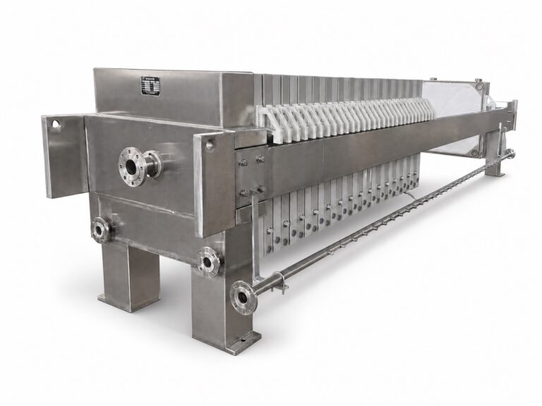
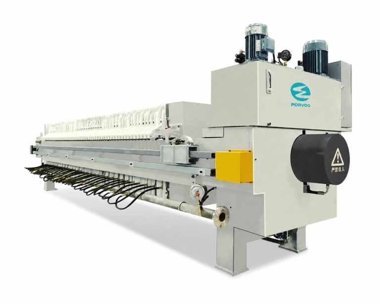
A feed pump sized only by motor power tells the buyer little about whether it will actually fill a plate-and-frame press the way the process requires. The pump, the piping between it and the press, and the instruments that govern how the system behaves across a batch form one interface, and decisions made in isolation at each point tend to surface later as mismatches between what the press needs and what the feed system delivers.
Start with the press fill profile and slurry behavior
| Duty input | Project definition to establish | Feed-system decision it supports |
|---|---|---|
| Press fill sequence | Required sequence for filling the press | Establishes the basis for the flow and pressure profile across the batch |
| Slurry solids variability | Expected variation in slurry solids | Shows the range of slurry behavior that the duty and control approach must address |
| Operating schedule | Required batch timing and operating schedule | Connects pump duty to the intended operating pattern |
| Motor power | Proposed motor power | Can be checked against the defined duty, but does not establish that duty by itself |
The press fill sequence is the starting reference for feed-system duty because it describes how the chambers need to receive slurry over time, not just how much slurry must eventually be moved. A press that fills in distinct phases requires the feed system to support each phase rather than a single averaged flow and pressure value. Where the fill sequence calls for a lower-pressure, higher-flow stage followed by a higher-pressure, reduced-flow stage as the chambers approach capacity, the pump and its control strategy must be able to follow that change, not simply deliver a nominal rating.
Slurry solids variability changes this picture further. A slurry stream that varies in solids content across a shift, a batch, or a source changes how the chambers fill, how quickly resistance builds, and how the pump responds as the system works against rising back-pressure. A feed system selected against a single assumed solids value may perform acceptably at that value and poorly outside it, which is why the expected range of solids concentration belongs in the duty definition rather than being treated as a secondary detail confirmed later.
The operating schedule ties these two factors to how the plant actually runs the press. A press cycled multiple times within a period behaves differently, from a wear and control standpoint, than one operated less frequently with longer intervals between fills. The schedule does not change the physics of filling a chamber, but it does change how much the feed system’s control approach and mechanical duty are exercised, and it affects how the buyer and supplier think about component selection for the service life expected.
Motor power follows from these inputs; it does not substitute for them. A proposed motor power can be checked against a stated fill sequence, solids range, and schedule, but a motor power alone carries no information about how the pump needs to behave as the batch progresses. Buyers preparing a feed-system specification get more useful supplier dialogue by presenting the fill sequence, solids variability, and schedule first, and treating any proposed power or pump model as something to verify against those conditions rather than as the starting point.
Pump duty and control across the filtration cycle
A plate-and-frame cycle is not a constant-duty operation, and the feed pump’s required behavior changes as the chambers fill. Early in the cycle, the press chambers offer relatively open flow paths, so the pump may be required to deliver flow at comparatively low pressure. As cake begins to build against the cloth and the available flow path narrows, resistance increases, and the same pump must be able to maintain the filtration process at reduced flow and increased pressure without the control strategy forcing an abrupt or poorly managed transition. This is a distinct requirement from simply confirming that a pump can reach a maximum rated pressure; what matters is whether the control approach lets the pump move through the full range the cycle requires, in the sequence the cycle requires it.
This is also why the feed pump’s duty cannot be fully defined by the pump supplier or the press supplier working separately from the other’s inputs. The press defines the chamber geometry and the resistance the system will present as filtration progresses; the feed-pump side must translate that resistance profile into a flow and pressure curve the pump and its control components can follow. Where the control approach relies on throttling, bypass, variable-speed operation, or a combination, the choice changes how the pump responds to the same underlying chamber-resistance profile, and it changes what instrumentation and interlocks are needed to manage that response safely. A system designed around one control method does not necessarily transfer cleanly to another without revisiting the duty profile.
Agreeing this profile with the press supplier, rather than assuming it from general pump catalog data, is the practical step that connects the fill-sequence information to a workable feed-system design. Where the batch includes stages such as pre-coat, bulk fill, and a final pressing or consolidation stage, each stage can carry its own flow and pressure expectation, and the control approach needs to be defined across all of them rather than tuned only for the bulk-fill condition. A feed system verified only against the easiest portion of the cycle may still fail to perform as chambers approach their filled condition, which is the point in the cycle most sensitive to how well the pump and its control respond to rising resistance.
Pipe routing, valves, drains and cleanout access
| Interface element | Project detail to show | Review decision |
|---|---|---|
| Pipe routing | Complete slurry feed route | Confirm that the pump-to-press route and its interfaces are defined |
| Suction conditions | Conditions at the pump suction | Check the pump duty against the actual inlet conditions |
| Recirculation or bypass | Whether either path is included and how it is routed | Confirm the alternate flow path used by the control approach |
| Isolation | Isolation points and required valve states | Confirm how the feed line is separated at the relevant operating or access condition |
| Drainage | Drain points and drainage route | Confirm how the feed line will be drained |
| Flushing | Flushing connections and flow path | Confirm that the planned flushing route is defined |
| Wetted materials | Materials exposed to the slurry | Check compatibility with the project slurry |
| Grit exposure and cleanout | Exposed locations and the access provided for cleanout | Check that grit exposure and physical cleanout access are addressed together |
The piping between the feed pump and the press is not a passive connection; it is part of how the system is operated, isolated, drained, and cleaned, and each of those functions depends on decisions made at the routing stage. The complete slurry feed route, including its length, elevation changes, and the fittings along it, affects the pressure the pump must overcome before slurry even reaches the press, which is why suction and discharge routing need to be reviewed against the duty established for the pump rather than assumed to be neutral.
Suction conditions deserve particular attention because a pump duty calculated without reference to actual inlet conditions, such as the available suction head or the presence of entrained air or settled solids at the suction point, can understate what the pump needs to do to maintain stable delivery. Where recirculation or a bypass path is part of the design, its routing determines how the system behaves when the press is not accepting full flow, such as during a transition between cycle stages, and that routing needs to be defined as part of the piping layout rather than left as an assumed capability of the pump.
Isolation, drainage, and flushing are related but distinct functions. Isolation determines how the feed line is separated from the press or the pump for maintenance or changeover; drainage determines how residual slurry is removed from the line once isolated; flushing determines how the line is cleared of material between operating cycles or before maintenance access. Where any one of these is left undefined, the practical result is that operators improvise a method at the time it is needed, which is not the same as having a planned, repeatable approach built into the piping design.
Wetted-material compatibility and grit exposure connect the piping design back to the actual slurry composition. A slurry with abrasive or granular content changes which materials remain suitable for pipe, fittings, and valve trim over the system’s operating life, and it also changes where cleanout access needs to be provided, since grit tends to settle at specific points in a routing layout rather than distributing evenly. Reviewing grit-related wear and cleanout access together, rather than as separate questions, better reflects how the two issues actually interact in service. Readers working through this review alongside related grit-removal planning for abrasive slurries will recognize the same interaction between material exposure and physical access.
Instrumentation and interlocks at the feed-system boundary
The instruments placed at the feed-system boundary are what let the control approach defined for the filtration cycle actually function, and what let operators and safety systems know the real state of the system rather than an assumed one. Flow and pressure measurement at or near the pump discharge gives the control system the information it needs to move through the cycle’s stages in sequence, and the choice of where these instruments sit, relative to isolation valves or bypass connections, affects whether the reading represents what is actually entering the press or only what the pump is producing before any diversion.
Level or similar status information on the slurry source feeding the pump matters for a related but separate reason: it protects the pump from operating against an inadequate supply, which is a mechanical and safety concern distinct from the filtration-control question of matching flow and pressure to the cycle stage. Conflating these two instrumentation purposes, supply protection and cycle control, risks a design where one function is addressed and the other is assumed to be covered by the same signal when it is not.
Interlocks tie these instruments to required valve states and to the pump’s run condition. Where isolation valves must be in a defined position before the pump is permitted to start, or where a bypass path must open automatically if flow cannot reach the press, the interlock logic depends on having reliable instrument signals at the correct points in the piping, which is why the instrumentation and the piping and valve layout cannot be finalized independently of each other. A buyer defining this boundary should treat the instrument list and the required valve states as one combined interface rather than separate specifications handed to different parties, since a signal without a corresponding defined valve state, or a valve state without a signal confirming it, leaves a gap in how the interlock actually protects the system.
Supplier interface data required before release for manufacture
| Release item | Evidence required in the interface package | Boundary confirmed |
|---|---|---|
| Feed-system duty basis | Required press fill sequence, slurry solids variability and operating schedule | Duty is based on the planned process rather than motor power alone |
| Batch pump profile | Required flow and pressure profile, with the control changes across the batch | Pump operation is agreed with the press supplier across the full cycle |
| Piping and valve interface | Suction conditions, recirculation or bypass, isolation, drainage, flushing and required valve states | The feed route and its operating states are defined as one interface |
| Instrument interface | Instruments included at the feed-system boundary | The measurement interface is identified before manufacture |
| Slurry-contact basis | Wetted-material compatibility and grit exposure | Material selection and grit-related access are tied to the project slurry |
| Cleanout provision | Required cleanout access | Physical access is included in the interface definition |
| Equipment boundary | Separate identification of the slurry feed pump and the press closing hydraulic system | The two pump systems are not treated as one duty |
Before a feed-pump and piping package is released for manufacture, the project needs to show that each of the preceding decisions has been made deliberately rather than left to default assumptions. This is also the point where the project information a buyer supplies enters Porvoo’s configuration and quotation review process: the fill sequence, slurry variability, operating schedule, piping interface decisions, and instrument list together give a supplier enough basis to confirm that a proposed plate and frame filter press and its associated feed system match the stated duty, rather than reviewing the pump and the press as unrelated line items.
The duty basis, covering fill sequence, solids variability, and schedule, needs to be present as stated information, not inferred from a motor power figure. The batbatch pump profile needs to show the agreed flow and pressure changes across the cycle, confirming that the press supplier and the feed-system supplier have reconciled their respective inputs. The piping and valve interface needs to document suction conditions, recirculation or bypass routing, isolation points, drainage, and flushing as one coordinated package, since a release package that treats these as separate drawings from separate disciplines tends to reproduce the same coordination gaps the design review was meant to catch. The instrument interface needs to identify what is measured and where, consistent with the interlock logic the system depends on.
Material and access decisions complete the package: wetted-material compatibility and grit exposure need to be confirmed against the actual project slurry, and cleanout access needs to be shown as a physical provision in the layout, not assumed to be available because a drain connection exists elsewhere. Finally, the release package needs to identify the slurry feed pump and the press closing hydraulic system as separate equipment with separate duties; the two are both part of a plate-and-frame installation, but conflating their specifications, or assuming one supplier’s data covers both, is a common source of a release package that looks complete without actually containing complete information. Where the project has already worked through sizing questions such as those addressed when sizing a press for ceramic or stone slurry, that same data set gives the feed-system review a consistent basis to check pump duty against, rather than starting the feed-pump question from an unrelated assumption.
Frequently Asked Questions
Q: Can feed-pump quotations be compared by motor power and rated flow alone?
A: No. Compare each proposal against the same press fill sequence and required flow, pressure, and control profile across the batch, using the project’s slurry solids variability, suction conditions, and operating schedule. Motor power can then be checked against that defined duty, but it does not establish the duty by itself.
Q: When should a recirculation or bypass route be included?
A: Include one only when the planned control approach requires an alternate flow path. Define the condition in which it is used, its complete route, and the valve states for each relevant operating or access condition; resolve those points with the press supplier before the piping interface is released.
Q: What should be verified before an existing slurry feed line is reused?
A: Record the actual suction conditions, complete route, isolation points, drainage and flushing paths, wetted materials, grit exposure, and cleanout access. Then check those conditions against the proposed batch profile and project slurry, and keep reuse conditional until any mismatch is resolved.
Q: Which project changes should trigger a fresh pump-and-piping review?
A: Recheck the interface when the press fill sequence, expected solids variability, operating schedule, suction conditions, slurry compatibility basis, or grit exposure changes. Each can alter the duty, control approach, material check, or access requirement on which the original decision was based.
Q: How should the slurry feed pump be kept separate from the press closing hydraulic system in an RFQ?
A: Identify the slurry feed pump as its own equipment scope with its own duty basis, piping and valve interface, instruments, and control profile. List the closing hydraulic system separately so its function and data are not used as a substitute for the slurry feed-system definition.