Retrofitting filtrate recovery onto a dewatering circuit that already runs raises a question before any equipment is chosen: does the existing circuit actually have the spare hydraulic and solids capacity to support a new recovery loop, or will the retrofit simply move a bottleneck somewhere else? Getting this wrong costs more than a resized pump — it can destabilize a dewatering process that was previously balanced. The answer depends on what the current circuit is doing with water and solids today, not on what the recovery target is assumed to be.
Baseline the Existing Dewatering and Water Balance
| Baseline | What to establish in the existing circuit | Decision it informs |
|---|---|---|
| Solids balance | How solids move through the current dewatering circuit | Equipment selection for the retrofit |
| Water balance | How water moves through the current dewatering circuit | The recovery target and required collection route |
A retrofit decision starts with the circuit as it runs now, not as it was designed. Dewatering equipment that has been in service accumulates its own operating pattern — cycle times, cake behavior, filtrate clarity, and pump duty all settle into whatever the feed and maintenance history have produced. Any recovery target set without reference to that pattern risks being either unachievable or unnecessarily conservative.
Two separate balances need to be established, and they inform different decisions. The solids balance describes how solids move through the circuit: where they concentrate, where fines escape into filtrate, and how that distribution shifts with feed variability or filter condition. This balance matters most for equipment selection, because a recovery retrofit built for a circuit whose filtrate currently carries variable solids will need different collection and conditioning capability than one built for a circuit producing a cleaner, cleaner, more consistent stream. The water balance describes how water moves through the circuit: filtrate volume, wash water, overflow events, and where water currently exits the system without being accounted for. This balance sets the recovery target itself and identifies which collection route can physically capture that volume without disrupting existing drainage.
Where the solids balance shows that filtrate quality already varies with upstream conditions — feed moisture, cake formation, filter media condition — the retrofit needs to plan for that variability rather than design around a single assumed filtrate quality. Where the water balance shows that a meaningful share of water already leaves through paths that were never instrumented or sized for recovery, the retrofit scope grows to include capturing that path, not just adding storage and a pump to an existing collection point.
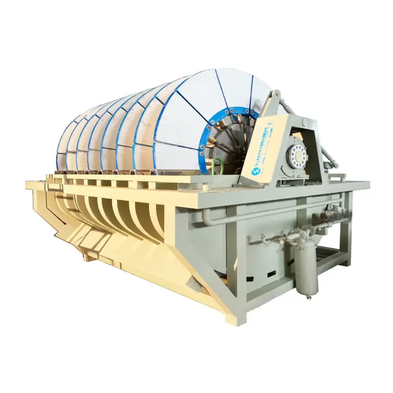
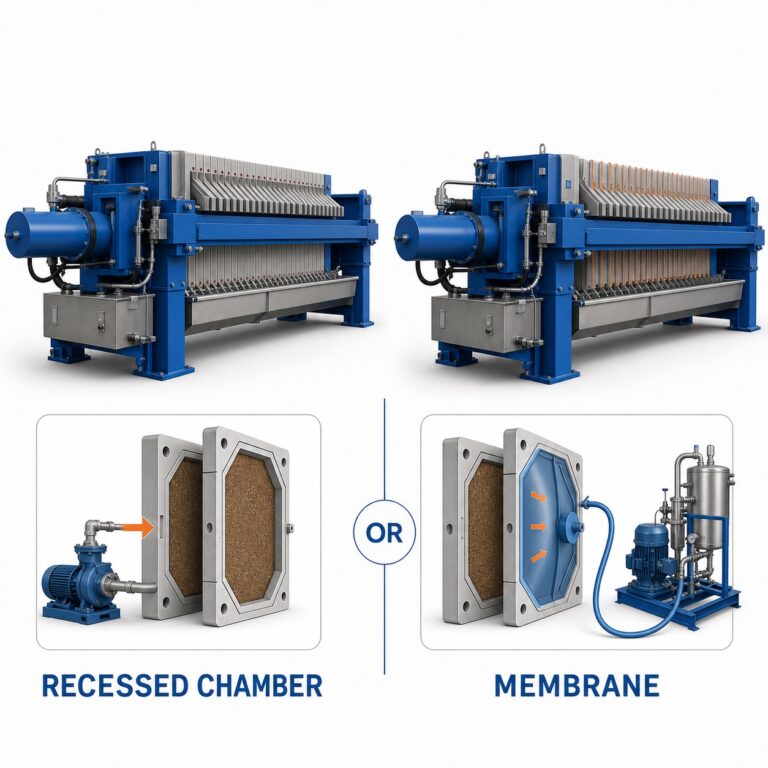
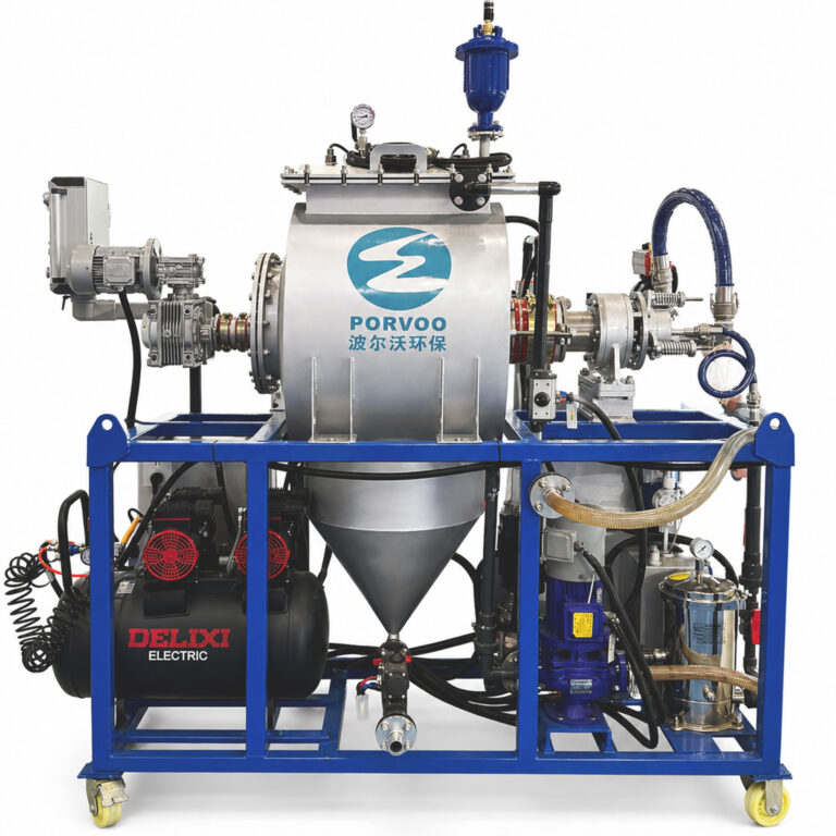
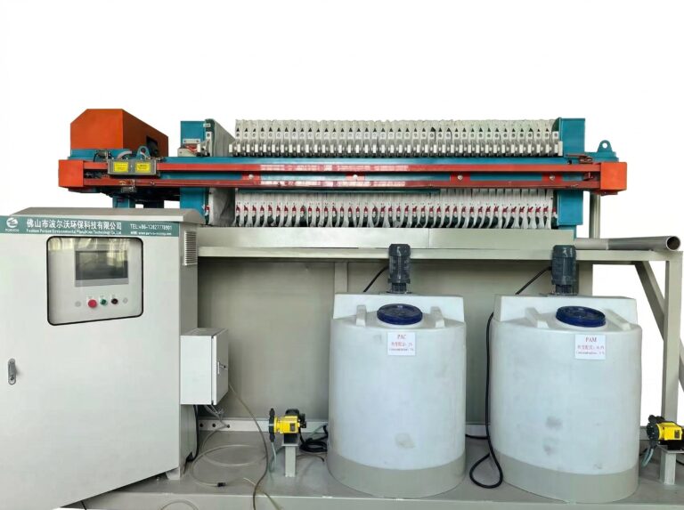
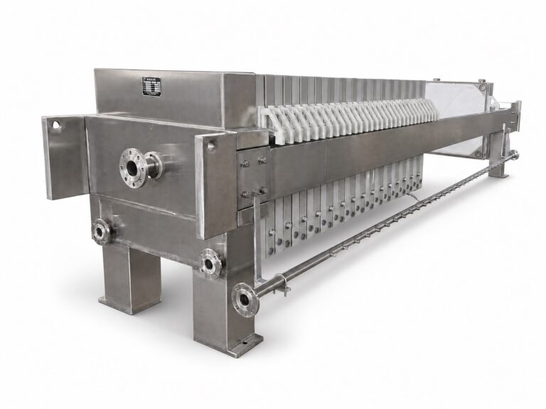
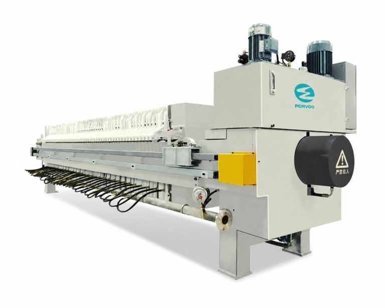
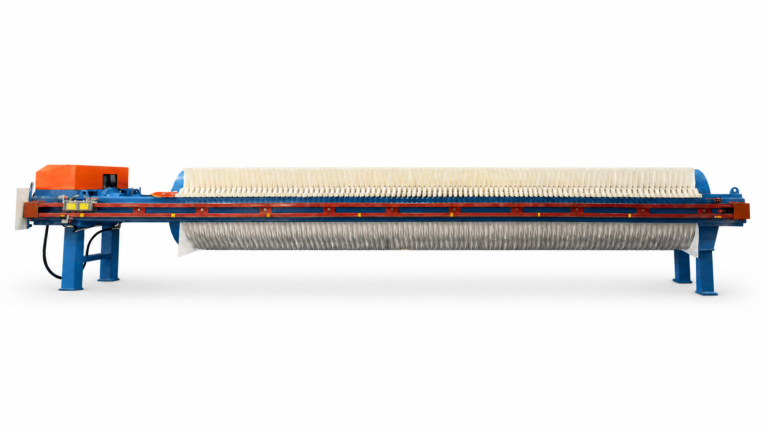
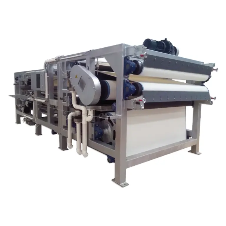
This baselining step also determines whether the retrofit is primarily a plumbing and controls exercise or whether it requires reconsidering the dewatering equipment itself. A circuit running Industrial Filter Presses for Sludge Dewatering, for example, produces filtrate in a pattern tied to press cycle time and cake formation, which differs from the more continuous filtrate pattern of a rotary or disk-type dewatering unit. The retrofit design has to match the collection and storage approach to whichever pattern the baseline reveals, rather than assuming a generic steady-state flow.
Define the Reuse Destination and Its Quality Envelope
| Quality check | Supported measurement reference | How to use the result | Evidence boundary |
|---|---|---|---|
| Suspended solids | ISO 11923:1997, determination by glass-fibre filtration | Compare the measured result with the quality envelope for the intended destination | The method does not set a universal reuse limit or guarantee treatment performance |
| pH | ISO 10523:2008, determination of pH in water and wastewater | Compare the measured result with the quality envelope for the intended destination | The method does not set a universal reuse or discharge limit |
The recovery target only becomes meaningful once there is a defined destination for the recovered filtrate. “Recover and reuse” is not itself a specification — process makeup water, wash water, dust suppression, or another internal use each tolerates a different range of suspended solids, dissolved constituents, pH, and variability. The destination, not the filtrate source, sets the quality envelope the retrofit must satisfy.
This is where general water-quality reasoning becomes project-specific. Reused process water can carry forward variables that affect a receiving process in ways that are not obvious from the filtrate’s appearance alone — a point reflected in Metso’s discussion of water quality and recycled reagents in flotation return water, which frames process-water characteristics as variables requiring evaluation against the specific receiving process rather than assumptions that any recovered water is interchangeable. The same logic applies outside mineral processing: a destination tolerant of elevated suspended solids has a very different envelope than one sensitive to fine particulates or chemical carryover.
Two measurements anchor this evaluation without over-specifying it. Suspended solids, measured by the glass-fibre filtration method in ISO 11923:1997, characterizes particulate carryover in the filtrate. pH, measured per ISO 10523:2008, characterizes a basic chemical property relevant to many receiving processes. Both are measurement methods only — neither standard sets a reuse or discharge limit, and neither guarantees that filtrate meeting a given reading is suitable for a particular destination. The limit comes from the destination’s own tolerance, which the project team must define before testing has any decision value.
Where the destination is a process step sensitive to solids carryover, the quality envelope will be narrow and the retrofit’s collection and conditioning design needs to be built around hitting it consistently. Where the destination tolerates broader variability, the envelope is wider and the retrofit can prioritize simpler collection and routing over tight water conditioning.
Route Collection, Storage, Pumping, and Overflow Interfaces
Once the baseline and the destination envelope are defined, the retrofit becomes a routing problem: how does filtrate get from its point of generation to a storage point, and from storage to the destination, without disrupting the dewatering circuit it is being added onto. Each interface in this path — collection, storage, pumping, and overflow — has to be sized and positioned against the constraints the existing circuit already imposes, not against a clean-sheet design.
Collection has to match the filtrate generation pattern identified in the baseline. A circuit that produces filtrate in batches, tied to a dewatering cycle, needs collection capacity sized for the batch volume and timing, not an average flow rate. A circuit with more continuous filtrate generation can work with smaller collection buffers but needs the downstream path sized for sustained flow. Storage sits between generation and reuse and absorbs the difference between how filtrate arrives and how the destination accepts it — if the destination draws water intermittently or at a different rate than filtrate is generated, storage capacity is what reconciles the two without forcing either side to match the other’s timing.
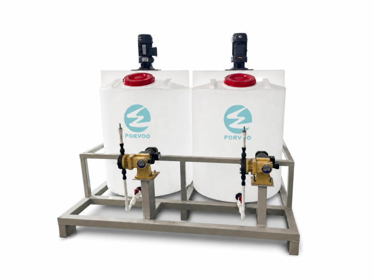
Pumping has to be sized not only for flow and head but for compatibility with whatever residual solids the baseline showed in the filtrate, since a pump selected for clean water duty may not hold up against a stream carrying fines. Overflow protection is the interface most tied to retrofit risk specifically: because the recovery loop is being added to a circuit that already has an established water balance, any failure or restriction in the new collection, storage, or pumping path needs a defined overflow route back to the circuit’s existing handling, rather than an unplanned discharge or backup into the dewatering process itself. Where the existing circuit already has spare capacity in its original water or filtrate handling, that path can serve as the overflow destination. Where it does not, the retrofit has to create one, which changes the scope and the tie-in points the project needs to plan around.
Add Monitoring, Diversion, and Conditional Polishing Interfaces
| Interface or response | When it becomes relevant | Decision use |
|---|---|---|
| Monitoring | Recovered filtrate is being evaluated for a defined destination | Track the water-quality variables that matter to that receiving process |
| Segregation or diversion | The stream has not yet been shown to suit the intended destination, or process risk remains | Keep the stream available for separate handling while suitability is assessed |
| Conditional polishing | Testing identifies a destination-specific water-quality concern | Evaluate a cleaning route for that concern; polishing is not assumed to be universally required |
Not every filtrate recovery retrofit needs the same water-management response, and treating monitoring, diversion, and polishing as a fixed sequence applied to every project overstates what the evidence supports. Each becomes relevant under a different condition, and the project should add only what the destination and the baseline actually require.
Monitoring becomes relevant once a destination has been defined, because it is the mechanism that confirms the filtrate meets that destination’s quality envelope on an ongoing basis rather than only at the point the retrofit was commissioned. What gets monitored follows from which variables matter to the receiving process — a destination sensitive to solids carryover needs that variable tracked; a destination sensitive to chemical characteristics needs a different variable tracked. Monitoring without a defined destination has nothing to be judged against.
Segregation or diversion becomes relevant wherever the filtrate’s suitability for the intended destination has not yet been established, or where a known process risk makes routine return premature. This is a protective interface, not a permanent one: its purpose is to keep the stream available for separate handling while testing and trial operation build confidence, so that an unsuitable stream never reaches the destination by default while the retrofit is still being verified.
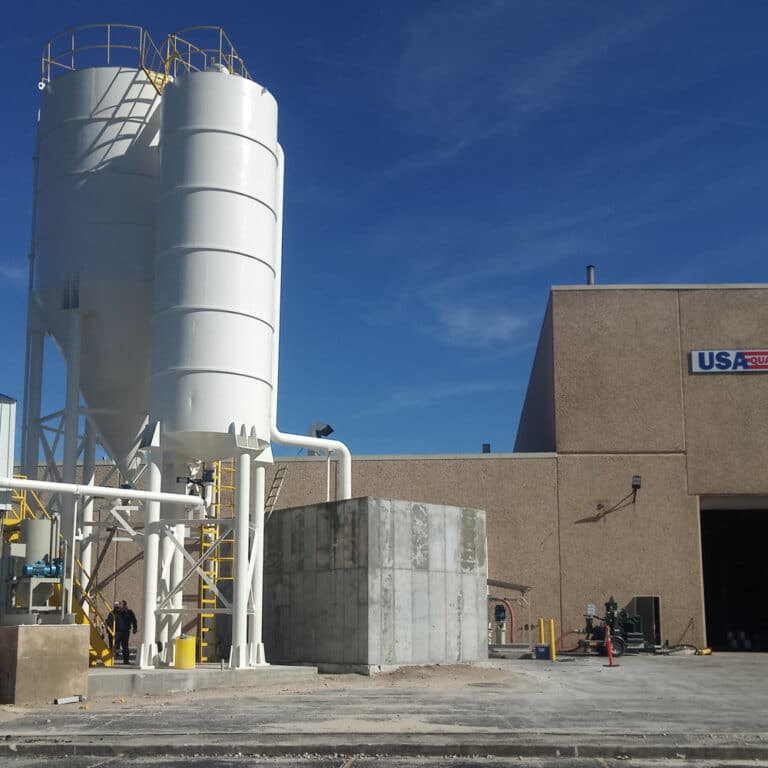
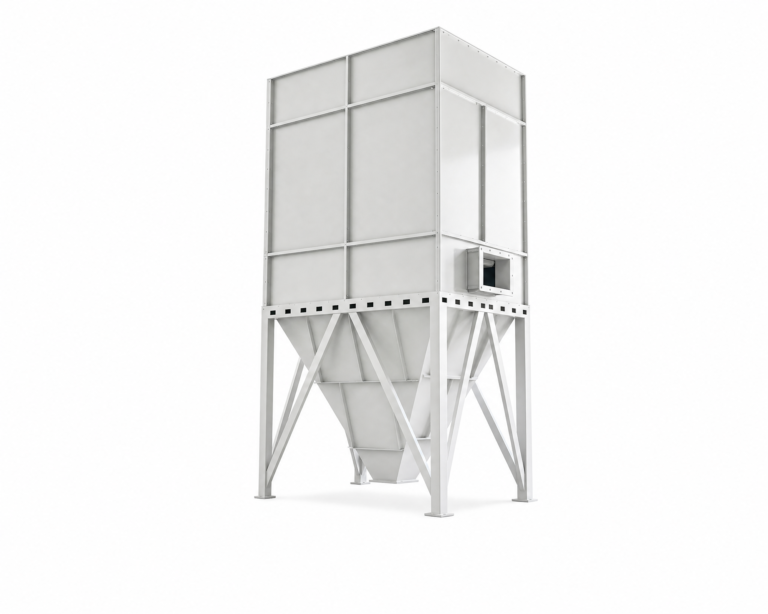
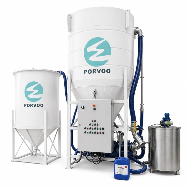
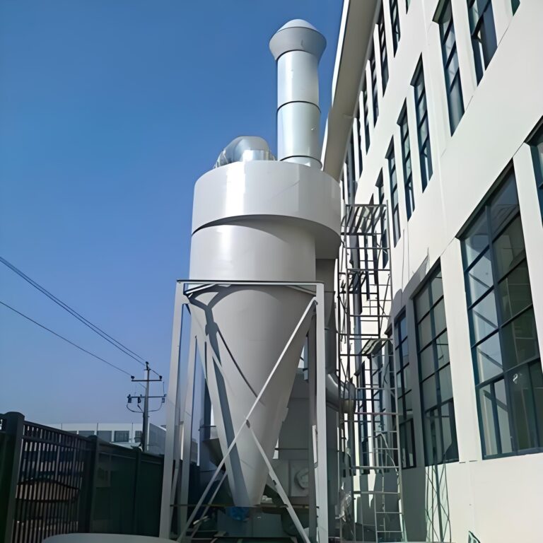
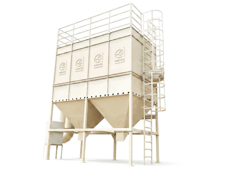
Conditional polishing becomes relevant only where testing identifies a specific water-quality concern that the destination cannot tolerate. This is where the quality envelope and the measurement results meet directly — if suspended solids or pH readings fall outside what the destination tolerates, a cleaning route addressing that specific concern is evaluated, drawing on equipment such as a Vertical Sedimentation Tower for Wastewater Recycling where settling or clarification is the relevant mechanism for the concern identified. Polishing is not assumed to be required for every retrofit; adding it where testing shows no concern adds cost and complexity without a corresponding quality need.
Plan Tie-Ins, Controls, Utilities, and Shutdown Work
Routing and conditional water-management interfaces define what the retrofit needs to do; this section concerns how that gets built into a circuit that is already operating. Tie-in points, control integration, and utility connections all have to be planned against the existing circuit’s operating schedule and physical layout, because a retrofit that requires extended downtime or disrupts an unrelated process line carries a cost the project has to weigh before committing to a design.
Tie-in points — where new piping, pumps, or storage connect into existing collection or discharge infrastructure — determine how much of the retrofit can be installed without interrupting dewatering operation. Where the existing circuit has accessible, underutilized connection points, tie-ins can often be completed with limited interruption. Where the circuit’s layout leaves no such access, the retrofit may require a planned shutdown window, which changes both the sequencing of the work and how much can be verified before the circuit returns to service.
Controls integration determines whether the new recovery loop operates as an independent system that the operating team monitors separately, or whether it is folded into the existing dewatering circuit’s control logic so that diversion, pumping, and overflow responses happen automatically in coordination with the dewatering process itself. The choice depends on how tightly the recovery loop’s behavior needs to track the dewatering circuit’s own cycle — a circuit with batch-driven filtrate generation benefits more from integrated control than one with steady, continuous flow.
Utilities — power for new pumps, instrumentation signal runs, any air or dosing utilities a conditional polishing interface might require — need confirmation against what the existing site can supply at the tie-in location, since adding load at a point with no spare capacity changes the retrofit’s scope before any water-handling equipment is even installed.
This is also the stage where the project information the buyer assembles — baseline data, destination requirements, tie-in constraints, and utility availability — becomes the basis for a configuration and quotation review, since equipment sizing for the recovery loop depends on exactly these site-specific inputs rather than on a generic specification.
Verify the Retrofit With a Staged Operating Trial
| Trial gate | What to verify | Decision boundary |
|---|---|---|
| Temporary diversion available | Filtrate can be diverted during the staged trial | Begin verification without assuming routine return is ready |
| Hydraulic behavior checked | The retrofit behaves as intended within the operating dewatering circuit | Continue evaluation only after hydraulic behavior is verified |
| Receiving-process stability checked | The intended destination remains stable during the trial | Move toward routine return only after receiving-process stability is verified |
A retrofit should not move to routine operation on the basis of design calculations alone, because design assumptions and actual operating behavior are different kinds of evidence. A staged trial is what converts the design into a verified system, and it depends on temporary diversion being available throughout.
Diversion has to be in place before the trial begins, not added if something goes wrong. Its presence means the retrofit can be tested without committing the dewatering circuit or the receiving destination to accept recovered filtrate before its behavior is understood. This reverses the burden of proof appropriately: the retrofit must demonstrate stability before it is trusted with routine return, rather than being trusted by default and diverted only on failure.
With diversion in place, the first verification is hydraulic behavior within the operating dewatering circuit — confirming that collection, storage, pumping, and overflow interfaces behave as intended under the real, possibly variable, filtrate generation pattern rather than the averaged pattern used in design. Where hydraulic behavior deviates from what was planned, the project needs to resolve that before any water reaches the destination, since downstream stability can’t be meaningfully assessed on top of an unverified hydraulic path.
Once hydraulic behavior is confirmed, the second verification is the stability of the receiving process itself during trial operation. Where the destination is a process step, its own behavior during the trial — not just the filtrate’s measured quality — is the evidence that determines whether routine return is appropriate. A destination can receive filtrate meeting its quality envelope on paper and still show instability during an actual trial if some interaction was not anticipated in the baseline or destination-quality work; this is why the trial, not the design, is the final gate. Only after both hydraulic behavior and receiving-process stability are verified does the project have grounds to move toward routine return, and even then the diversion capability established for the trial remains a relevant asset for any future period when conditions in the dewatering circuit or the receiving process shift beyond what the original baseline captured.
Frequently Asked Questions
Q: Is a filtrate recovery retrofit simply a return-water pump?
A: No. Treat it as a system that connects collection, storage, pumping, overflow handling, controls, and tie-ins to a defined reuse destination. The design also needs a way to monitor and divert the stream while its suitability is being verified.
Q: Which reuse destination should be evaluated first?
A: Start with one receiving process whose required water-quality envelope can be stated and checked. Confirm that the stream can be diverted during evaluation, then compare measured filtrate quality and receiving-process behavior with that destination’s project-specific conditions before considering routine return.
Q: Do acceptable pH and suspended-solids results prove that recovered filtrate is reuse-ready?
A: No. Those measurements help characterize the stream against the chosen destination’s quality envelope, but their test methods do not set a universal reuse limit or establish receiving-process stability. Use them as part of the destination-specific assessment and staged operating trial.
Q: What information should be prepared for a retrofit request for quotation?
A: Provide the existing solids and water balance, the intended reuse destination and its quality envelope, current collection and overflow routes, available storage and pumping interfaces, tie-ins, controls, utilities, and shutdown constraints. Also define the proposed monitoring points, temporary diversion route, and the conditions that will be checked during the operating trial.
Q: Should all recovered filtrate be sent directly to routine reuse during commissioning?
A: No. Keep temporary diversion or segregation available while hydraulic behavior and receiving-process stability are checked in stages. Advance toward routine return only after the retrofit performs as intended in the operating circuit and the selected destination remains stable.