Most ceramic tile plants that struggle with wastewater reuse stability are not running the wrong equipment — they designed the system around the equipment they already understood rather than mapping the duty loop first. The practical result is a clarifier that handles average load but destabilizes under peak solids, dosing that chases pH swings it cannot anticipate, and filter cake returned to raw material batches without a moisture quality gate. These are not commissioning faults; they are sequencing faults that become expensive to correct after the system is built. What resolves them is fixing reuse-water quality targets, solids load by process step, dosing response requirements, sludge route, and return-point buffering before any equipment is specified — so that each unit is sized for the right problem in the right order.
Define the ceramic process steps that need recycled water
Water enters ceramic tile production at several points that carry meaningfully different solids loads and quality sensitivities. Spray-drying slurry preparation uses the largest volume and tolerates moderate turbidity; glazing lines use smaller volumes but are sensitive to particle contamination that causes surface defects; press cleaning and floor washdown generate high-solids streams with coarser grit. Understanding which step the recycled water will serve is the first upstream decision — because sizing a treatment system to meet glazing-line quality when most of the return volume goes to slurry preparation results in over-treatment on one side and inadequate buffering on the other.
The solids character of ceramic wastewater introduces a specific operational risk before treatment even begins. Fine silt in the 300–500 mesh range settles rapidly when flow velocity drops, and any holding tank installed without continuous mechanical agitation will accumulate a settled bed. That settled solids layer does not simply reduce tank effective volume — it delivers inconsistent feed concentration to coagulation dosing, causing the dosing controller to operate against a moving target. Systems that are difficult to diagnose after commissioning often have this failure embedded at the equalization stage, not in the clarifier or press where the operator is looking.
The practical design implication is that the buffer tank before treatment must be treated as an active process unit, not passive storage. Continuous stirring sized for the 300–500 mesh particle density keeps the feed suspension homogeneous, which stabilizes every downstream stage. Skipping it to reduce capital cost often produces a system that passes acceptance tests on commissioning day — when tanks are freshly filled — but degrades within weeks as solids accumulate.
Map grit removal dosing sedimentation filtration and sludge handling
The sequence of treatment stages matters as much as the stages themselves. Each unit in the chain protects the units downstream: grit removal before coagulation reduces abrasion in dosing pumps and coagulation chambers; coagulation before clarification aggregates the colloidal fines that a plain settling tank cannot capture by gravity alone. Skipping or reordering stages to reduce capital outlay consistently produces systems where the remaining stages are correctly specified but chronically overloaded.
| Escenario | What It Removes/Controls | Key Purpose |
|---|---|---|
| Flow equalization & pH adjustment | pH variation, flow surges | Provide stable feed to downstream processes |
| Primary screening & sedimentation | Coarse particles, grit, settleable solids | Protect downstream equipment from abrasion and clogging |
| Chemical coagulation | Fine colloidal solids, dissolved metals (via precipitation) | Aggregate particles for easier removal |
| Final clarification | Flocculated solids | Separate clear water from sludge |
| Filtración multimedia | Residual turbidity, fine particulates | Polish water to reuse quality |
| Deshidratación de lodos | Excess water from settled solids | Reduce sludge volume and prepare for reuse/disposal |
| Filtración por membrana | Dissolved heavy metals (e.g., zinc, lead) | Meet strict discharge/reuse limits |
A few sequencing decisions within this map carry consequences that are not obvious from the stage list alone. The presence of dissolved heavy metals — zinc and lead are common in ceramic glaze effluent — is a planning criterion, not a universal driver of membrane filtration installation. Whether membrane filtration is warranted depends on the site’s reuse or discharge limit for those metals; plants discharging to a municipal system with strict limits, or reusing water in applications where metal carry-over affects product quality, will need it. Plants with verified low-metal loads may find multimedia filtration sufficient, but that determination requires characterisation data, not assumption.
Vacuum filtration used in filter bag stages also requires a specific operational detail to function reliably: the trap between the vacuum pump and the receiving tank must retain enough liquid to maintain the vacuum seal. Allowing the receiving tank to empty completely breaks vacuum and interrupts the filtration cycle. This is an equipment specification point relevant to procurement — specifying the trap capacity and the low-level interlock is part of the design scope, not something left to the installer.
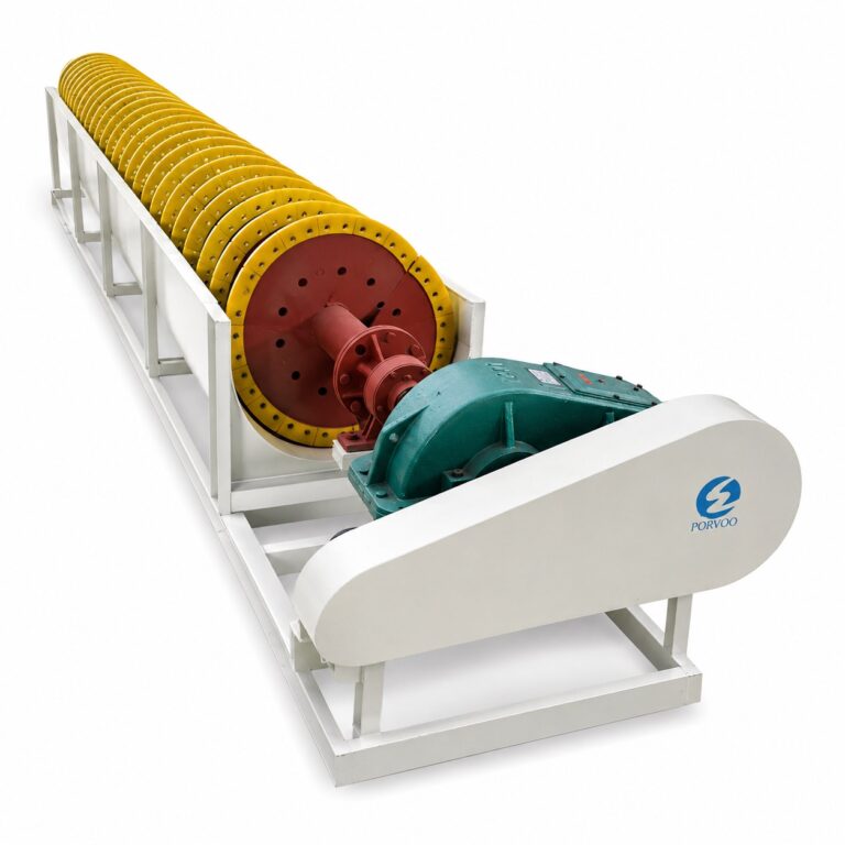
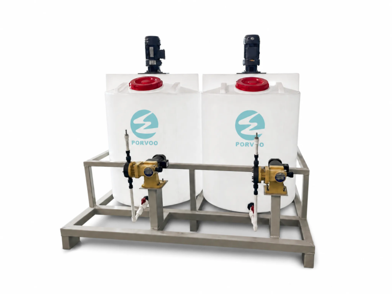
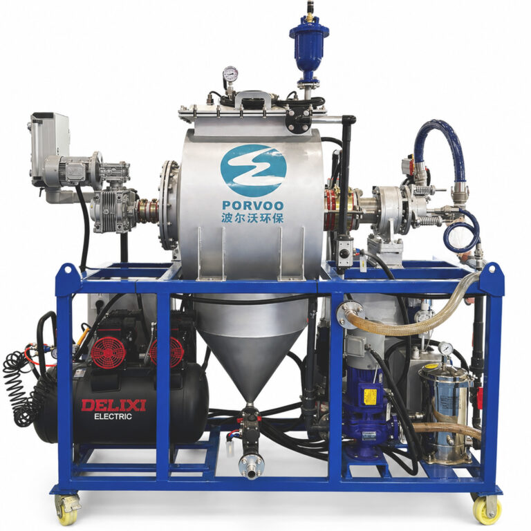
For equipment selection at the grit removal stage, the Eliminación de partículas grandes unit is designed specifically for the coarse-fraction loads common in ceramic and stone plants, and pairing it with an intelligent PAM/PAC dosing system provides the responsive coagulation control needed when feed solids vary across shifts.
Set reuse quality targets before selecting equipment
Equipment specifications are downstream of reuse targets, not upstream. Selecting a clarifier model or press capacity before defining the quality the recycled water must meet — turbidity, suspended solids concentration, pH range, conductivity — produces a system that may achieve clarifier manufacturer performance figures while delivering water that cannot actually be used in the intended process step without quality correction.
The benchmark data from operating ceramic facilities sets a useful envelope for what is achievable, rather than a minimum regulatory standard.
| Benchmark Source | Reuse Focus | Achieved Metric |
|---|---|---|
| Dal-Tile (5 plants) | Zero process wastewater discharge | Reuses >90 million gallons of water annually |
| Crossville | Solid byproduct recycling | Recycles 12 million lbs of filtrate, fired tile, and pre-consumer sanitary ware per year |
| Lea | 100% wastewater recycling | Reduces fresh water consumption by 60%; zero ecosystem discharge |
| Plant specification (general) | Filter cake reuse in tile body | Requires filter cake water content measurement before raw material addition to enable full resource reutilization |
What these figures imply for planning is not that every plant must match them, but that zero-discharge and high-reuse outcomes are design-sequence achievements rather than equipment achievements. Dal-Tile’s zero process wastewater discharge outcome required capturing every stream — including evaporative cooler condensate — and routing each one to a compatible return point. Lea’s 60% reduction in fresh water consumption required 100% wastewater recycling with a quality standard sufficient to allow unrestricted reuse. Neither outcome is reachable by specifying a larger clarifier; both require the reuse quality target to be fixed first, then the treatment train to be selected and sequenced to meet it.
The filter cake quality check — measuring moisture content before sludge is added to raw material batches — functions as a review gate within this target framework. If filter cake enters the tile body mix with uncontrolled moisture, it introduces an unquantified water addition that affects body consistency. This is not primarily a compliance question; it is a raw material control question, and the quality gate should be specified as part of the system design scope rather than left as an informal site practice.
Decide where filtrate returns and where it needs buffering
Return-point selection is where the closed-loop design either closes or breaks. Filtrate that meets the quality target for slurry preparation can return to that process directly. Filtrate that meets a lower standard — adequate turbidity but variable conductivity, for example — may be suitable for press cleaning or floor washdown but not for wet-process mixing. Defining these tiered return points during design allows the treatment system to be optimised for the dominant volume stream while routing lower-grade filtrate to appropriate secondary uses rather than discarding it.
A specific return-point decision documented at Dal-Tile illustrates the principle: condensate captured from roof evaporative coolers was found suitable as makeup water for extruded products, contributing over 500,000 gallons per year in fresh water savings. This is a design figure from a specific plant configuration, not a typical saving applicable to all facilities. Its value as a planning reference is to prompt the question — what non-traditional water sources exist on site, and which return points can they serve without quality pretreatment? Exhaust gas recovery systems represent another supplementary source: documented recovery at Grupo Lamosa reached approximately 40% of plant water use through exhaust gas condensation, a technically viable option specifically for water-scarce sites where conventional wastewater recycling alone does not close the gap.
The trade-off that is consistently underestimated at this stage is between return-point quality gates and buffer volume. Returning filtrate directly to wet-process mixing without confirming filter cake moisture content can introduce uncontrolled water into raw material batches, degrading body consistency in ways that may not surface until fired tile quality is reviewed — by which point several batches may have already been processed. Adding a buffer tank between the dewatering stage and the raw material feed allows moisture content to be sampled and confirmed before the material enters production. The cost of that buffer is footprint and capital; the cost of omitting it is periodic raw material batch variability that is difficult to attribute to the water system until a systematic investigation is run.
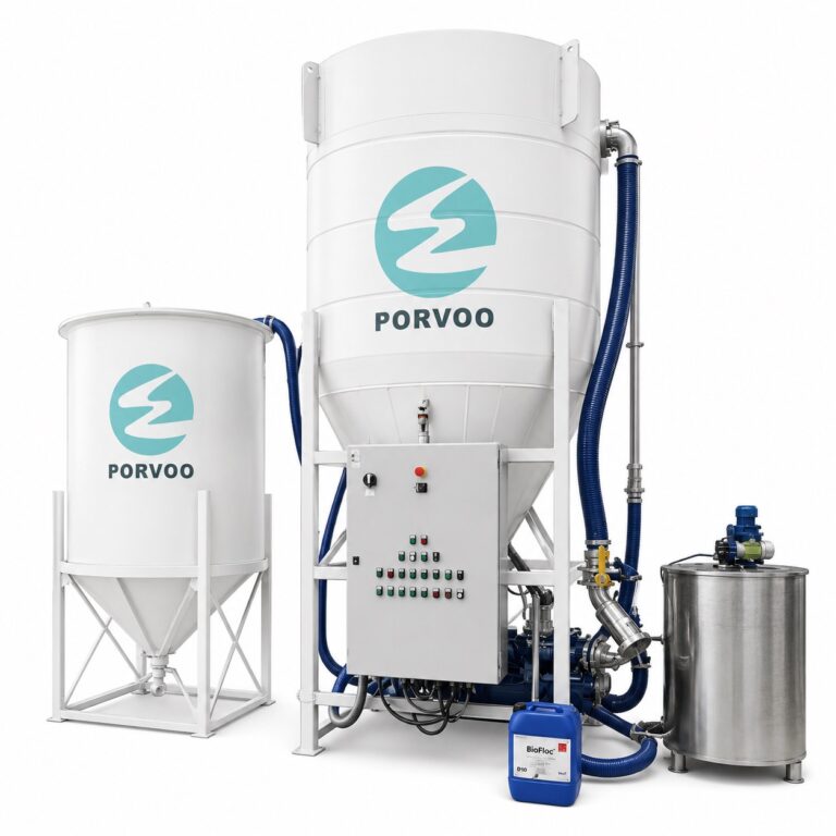
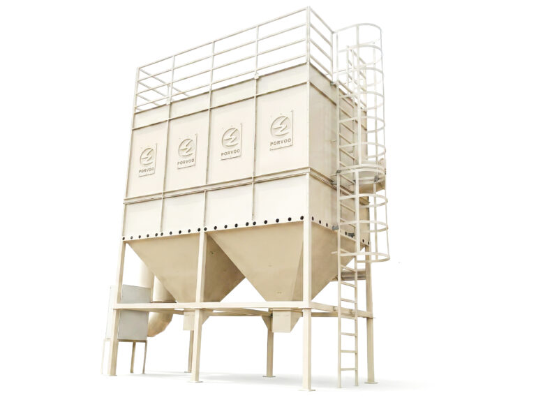
For the sedimentation stage between treatment and return, the Torre de sedimentación vertical is designed to handle the variable solids load typical of ceramic plant effluent while maintaining the clarified water quality needed for consistent reuse.
Connect automation to real pH turbidity and solids variation
Ceramic tile plant wastewater does not arrive at the treatment inlet at a steady state. Shift changes, glaze line colour changeovers, spray dryer wash cycles, and floor cleaning all generate flow pulses with different pH, turbidity, and solids concentration. A treatment system designed for average flow and average solids will perform adequately under those conditions but will underperform — or overdose — when actual conditions diverge from the design mean.
The automation logic for a ceramic wastewater system should be built around continuous measurement of the parameters most likely to vary with production activity: pH at the equalisation inlet, turbidity at the clarifier outlet, and suspended solids concentration at the dewatering feed. These three signals together give the control system enough information to adjust coagulant and flocculant dosing in response to real feed conditions rather than operating on a fixed dose schedule calibrated to average load. A fixed-dose approach will consistently overdose during low-solids periods — wasting chemistry and thickening sludge beyond target — and underdose during peak-solids events, allowing turbid water to pass through to the reuse stream or return tank.
The practical specification implication is that sensor placement and signal integration need to be defined at the process design stage, not added as instrumentation afterthoughts during construction. pH sensors placed downstream of the dosing point give feedback information too late to prevent a dosing error; they need to be upstream of dosing and upstream of coagulation contact time. Turbidity sensors at the clarifier outlet provide the acceptance signal for the return stream, but they should also trigger a divert valve that routes off-spec water back to the equalisation tank rather than allowing it to enter the reuse loop. ISO 46001:2019 provides a useful management system framework for structuring water efficiency monitoring across these measurement points, though it does not prescribe specific sensor configurations or control setpoints — those remain engineering design decisions.
The sludge dewatering end of the process also benefits from real-time monitoring. Filter press feed pressure, filtrate flow rate, and press cycle completion time together indicate whether the press is performing within its design range or whether cake is blinding the cloths — a maintenance signal that should trigger cloth inspection, not be ignored until throughput drops measurably.
Specify acceptance checks for water quality and sludge output
Acceptance checks at the system output serve two distinct purposes that are sometimes conflated: confirming the treated water meets reuse quality for the intended return point, and confirming the sludge meets specifications for its downstream route. These are separate quality gates with different measurement requirements, and designing them into the system scope from the start prevents the common outcome of commissioning a system that meets clarifier manufacturer performance data but has never been validated for actual reuse in the production process it was built to serve.
For the water side, the minimum acceptance parameters should correspond directly to the quality targets set for each return point. A glazing-line return stream needs turbidity and particle size confirmed; a slurry-preparation return stream needs pH and conductivity confirmed in addition to suspended solids. Measuring only what was easy to instrument during construction — often pH alone — leaves the reuse stream unqualified for its actual duty. The Ceramic Manufacturing Industry BREF provides useful process-reference guidance on general discharge ranges for ceramic plant effluent, but site-specific reuse quality limits need to be derived from the production process specifications of the return-point application, not assumed from a reference document.
For the sludge side, filter cake water content is the primary quality gate before the material can be added to raw material batches. This is a review check function: the measurement confirms that the dewatering stage has achieved its design output moisture level and that the cake will not introduce uncontrolled water into the tile body mix. If the moisture content is above specification, the appropriate response is to extend the press cycle, inspect the filter cloths, or divert the cake to a separate storage area — not to add it to the raw material stream on the assumption that production processes will compensate for the variation. Defining the acceptable moisture range, the measurement method, and the divert protocol at the design stage makes this a managed process step rather than an informal site check.
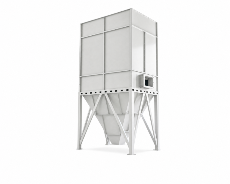
En Filtro prensa de membrana is directly relevant to achieving consistent cake moisture targets: the membrane squeeze cycle applies additional mechanical pressure after initial filtration, reducing final cake moisture content and narrowing the batch-to-batch variation that makes the quality gate difficult to hold with a standard recessed-plate press.
For further context on which specific treatment modules most affect reuse stability in ceramic and stone plants, the article on industrial wastewater treatment equipment examines this question at the module selection level.
Choose the next subtopic based on the plant bottleneck
Once the core treatment loop — equalization, grit removal, coagulation, clarification, filtration, dewatering, return-point routing — is designed and operating, the question shifts to what the plant’s actual constraint is. Not every plant has the same next problem, and misidentifying the bottleneck leads to investment in the wrong improvement.
Three distinct bottlenecks surface in practice. If the constraint is treated water volume — the plant cannot close the loop because it cannot recover enough water from the wastewater stream to reduce fresh water draw to target — then improving dewatering efficiency or adding a polishing filtration stage to qualify more water for reuse is the logical next step. If the constraint is sludge disposal — cake volume exceeds current disposal capacity or cost — then improving cake dryness through membrane pressing or optimising flocculant dosing to reduce sludge mass is the priority. If the constraint is water scarcity at the site level — total water availability is the binding limit, not treatment performance — then supplementary recovery sources become relevant. Exhaust gas condensation recovery, of the type documented at approximately 40% of plant water use in one industrial ceramics case, is a credible option for water-scarce sites where conventional wastewater recycling alone cannot close the supply gap. It is a valid next-step direction specifically for that bottleneck; it is not a default upgrade path for plants where the limiting factor is something else.
The bottleneck should be identified from operating data — specifically from the gap between current fresh water intake, current wastewater generation volume, current reuse volume, and current sludge disposal cost — before committing to a next-stage investment. Treating bottleneck identification as a data exercise rather than a product selection decision is what ensures the next capital outlay addresses the actual constraint.
A ceramic tile plant water recycling system that performs reliably at scale is the product of a design sequence that begins with process mapping and quality target-setting, not equipment procurement. The failure modes that are hardest to correct after commissioning — inconsistent dosing caused by unsettled solids in the buffer tank, uncontrolled moisture introduced at the raw material stage, off-spec reuse water that was never qualified for its return-point duty — share a common origin: the treatment system was specified before the loop it was meant to close had been fully defined.
Before advancing to equipment selection or vendor comparison, confirm that the following are fixed in writing: the quality target for each reuse return point, the solids load and particle size characterisation at each inlet, the filter cake moisture specification and the measurement method that gates its entry into production, and the sensor positions that give the dosing controllers real-time feed on actual conditions. Those decisions shape every downstream equipment choice; revisiting them after construction is what makes ceramic wastewater projects expensive to correct.
Preguntas frecuentes
Q: The article assumes a full wastewater stream to work with — what if the plant is still in design phase and has no operating data on solids load or flow volume?
A: Start from the production process specification, not wastewater measurements. Map each water-using step — slurry preparation, glazing lines, press cleaning, floor washdown — and estimate solids load from the raw material input rates and typical glaze formulation data. Use those figures to size the equalization and grit removal stages conservatively, then build in instrumented sample points so that the first months of operation generate the characterisation data needed to confirm or adjust the design. Designing to a process-derived estimate with measurement infrastructure built in is more reliable than waiting for operating data that does not yet exist.
Q: At what point does improving dewatering performance stop returning meaningful benefit — is there a practical moisture content floor for ceramic filter cake going back into raw material batches?
A: Yes, though the specific floor depends on tile body formulation rather than the dewatering equipment itself. The practical limit is the moisture content at which the cake introduces less batch-to-batch water variation than the raw material handling process already tolerates. Below roughly 20–25% moisture, a membrane filter press typically delivers consistent enough results for ceramic body reuse, but the acceptable range must be confirmed against the specific body recipe and spray-dryer inlet specification. Pushing for lower cake moisture than the raw material process requires adds press cycle time and energy without improving product consistency — the quality gate should be set at the formulation limit, not the equipment limit.
Q: How does this design approach change if the plant discharges treated effluent to a municipal sewer rather than targeting full reuse?
A: The treatment sequence is largely the same, but the quality targets shift from process-compatibility specifications to regulatory discharge limits. The coagulation and clarification stages still need to handle the same solids load; the difference is that the acceptance check at the clarifier outlet is measured against the municipal system’s inlet permit rather than the glazing-line or slurry-preparation tolerance. One practical consequence is that discharge-oriented plants have less incentive to optimise filter cake moisture for raw material reuse, which removes a key feedback loop that disciplines dewatering performance. Plants designed for discharge compliance alone tend to accumulate sludge disposal cost as a variable that was never controlled by design — something worth factoring into the long-term operating cost comparison before committing to discharge over reuse.
Q: Is exhaust gas water recovery worth evaluating at the same time as the core wastewater recycling system, or should it be treated as a separate later project?
A: Treat it as a parallel scoping exercise during design, but do not let it delay the core loop. The value of assessing it early is that exhaust gas condensate may qualify as a return-point source that reduces the volume the wastewater treatment system needs to recover — which can affect clarifier sizing and buffer tank volume. However, exhaust gas recovery requires kiln and dryer exhaust characterisation data that may not be available at design time, and its economics depend heavily on local water cost and scarcity. The practical approach is to reserve a return-point connection in the system design without committing capital to the recovery unit until the core loop is validated and water scarcity is confirmed as the binding constraint.
Q: Where does this type of system sit on the capital cost spectrum compared with a simpler settle-and-reuse arrangement — is the added complexity justified for a mid-size ceramic plant?
A: The added stages — equalization with agitation, coagulation dosing, sedimentation, filtration, and controlled dewatering — are justified when the reuse return point has a quality threshold that a plain settling arrangement cannot consistently meet. For a plant returning all recovered water only to floor washdown or press cleaning, a settle-and-reuse setup may be sufficient. For any plant returning water to glazing lines or slurry preparation, the quality gates those processes impose make the full treatment sequence a production reliability requirement, not an optional upgrade. The real cost comparison is not between simpler and more complex systems — it is between the capital cost of the complete system and the combined cost of fresh water purchase, discharge fees, batch defect rates from inconsistent reuse water, and the retrofit expense of adding treatment stages after a simpler system fails to hold quality. Evaluated over a five-year operating window, the full-sequence design is almost always less expensive for plants with any wet-process reuse duty.