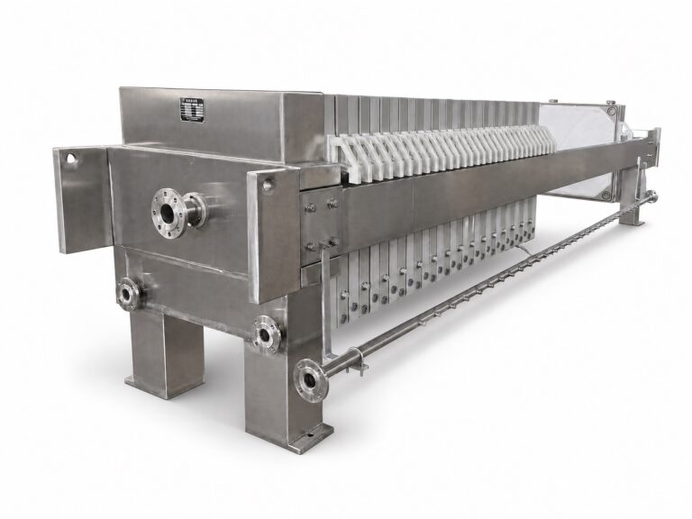
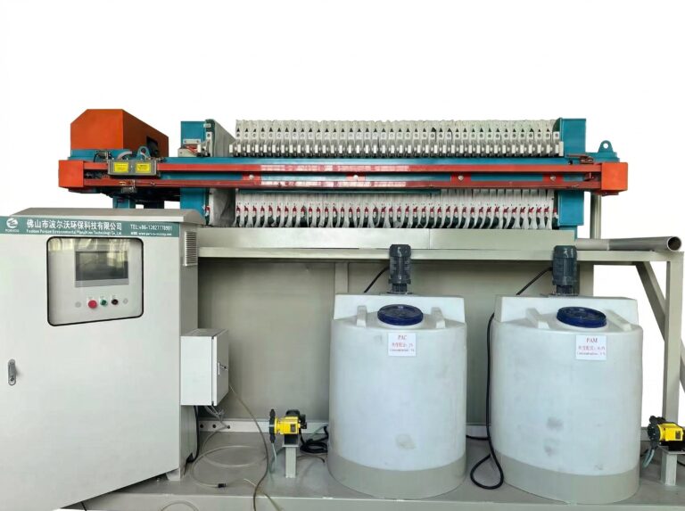
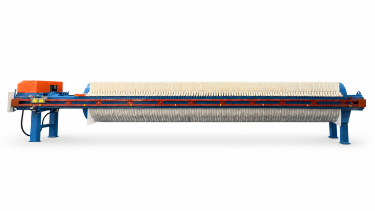
Choosing between open and closed filtrate discharge on a chamber press is not a cosmetic preference. It changes what an operator can see, what the piping scope includes, and what a project team must document before the equipment arrives on site. The decision deserves the same project-specific scrutiny as plate count or cloth selection, because the discharge arrangement determines how filtrate is observed, routed, contained, and verified for the life of the press.
What open and closed discharge change at the press
| Discharge arrangement | Selection priority | Requirement to define before selection | Supplier-specific point to verify |
|---|---|---|---|
| Open discharge | Individual-outlet visibility where plate-by-plate comparison is required | State which discharge points must remain visible and accessible | Confirm the actual plate and outlet arrangement; the word open does not establish identical observation points |
| Closed discharge | Contained routing through a header | State the required filtrate route and containment boundary | Confirm the actual manifold, valves, isolation points, and access arrangement |
An open discharge arrangement exposes filtrate at or near each outlet, so an operator standing at the press can see flow leaving individual plates. A closed arrangement collects filtrate into a header before it reaches any point where an operator would normally observe it. The difference is not simply visual; it changes what the press boundary includes. In an open arrangement, the press-side scope typically ends close to the plate outlet, and everything downstream of that point becomes a separate routing question. In a closed arrangement, the manifold itself is part of what the supplier offers, which means the boundary between equipment and site piping sits further downstream.
This has a direct consequence for how a buyer reads a quotation. Where plate-by-plate observation is the priority, the project needs to confirm that the offered arrangement actually exposes each outlet rather than grouping several plates before any visible point. Two presses can both be called “open discharge” while differing in how many outlets share a common visible drain point before individual flows become indistinguishable. Where containment is the priority, the project needs to confirm how much of the collected route sits inside the supplied equipment versus how much must be built by others.
The condition that changes the judgment is what the buyer actually needs from the press: diagnostic visibility into cloth or plate performance, or a contained route that limits operator contact and environmental exposure. Where frequent plate-level comparison is required, an open arrangement with confirmed outlet visibility supports that need directly. Where the filtrate stream requires containment from the plate face onward, a closed arrangement reduces the number of open transfer points, but only if the manifold, valves, and isolation points are specified rather than assumed from the word “closed” alone. Neither label guarantees a specific configuration; both require the actual plate, outlet, manifold, and valve arrangement to be confirmed against the project’s visibility and containment requirements before the choice is treated as settled.
Operator visibility and sampling access by arrangement
| Operator task | Requirement to state | Граница принятия решения |
|---|---|---|
| Observe discharge by plate | Identify which outlets must remain visible | Visibility must be confirmed for the offered plate and outlet arrangement |
| Compare discharge between plates | Identify which discharge points must be accessible for comparison | An open arrangement alone does not establish the required observation points |
| Collect filtrate samples | Identify the sampling point and required access | Sampling access must match the actual outlet or manifold arrangement |
| Reach the observation or sampling point | Define the access that operators need at the press | Confirm access against the supplier’s offered arrangement rather than the arrangement label alone |
Visibility and sampling are related but not identical requirements, and treating them as the same need can leave a gap between what the press provides and what operators are asked to do with it. Visibility is the ability to see that filtrate is discharging, and from where. Sampling access is the ability to physically reach a point and withdraw a representative portion of that stream. A press can offer one without the other: an outlet can be visible from a walkway without being reachable for sampling, or a sampling port can exist without being visible during normal operation.
Where operators need to compare discharge between plates, the project must identify which outlets require visibility and which require physical access, because these may not be the same set of points. A press offered as open discharge does not, by that label, establish that every plate is equally visible or equally accessible; outlet spacing, guarding, and platform layout all affect whether an operator can actually observe or reach a given point during a production run. This is a condition the buyer specifies, not a property that follows automatically from choosing an open arrangement.
Sampling introduces a further condition: the sample has to represent the filtrate at a meaningful point in the routing, not just at any open outlet. If the project requires a sample that reflects the combined stream rather than a single plate, an individual-outlet sampling point does not serve that purpose, and a manifold-level sampling point becomes necessary instead. Conversely, if the purpose is to isolate a problem to a specific plate, a combined sampling point after the manifold cannot answer that question, regardless of how accessible it is.
The practical consequence is that “visibility” and “sampling access” need to be stated as separate requirements, each tied to its purpose, before the discharge arrangement is selected or accepted. A requirement written only as “operators should be able to see the discharge” leaves open whether that means per-plate observation, combined-stream observation, or both, and the supplier cannot be expected to resolve that ambiguity from the single word.
Filtrate destinations, diversion, drainage, and containment
| Filtrate path or function | Project routing input | Использование решения |
|---|---|---|
| Выборка | Sampling point and its destination | Confirms that the selected route preserves the required sampling path |
| Reuse | Reuse destination | Defines the return path that the discharge arrangement must serve |
| Treatment return | Treatment-return destination | Defines where the filtrate route must reconnect to treatment |
| Off-spec diversion | Diversion destination | Shows the separate path needed when filtrate cannot follow its normal route |
| Дренаж | Drain destination | Defines the drainage connection that must be included in the routing plan |
| Spill handling | Containment destination | Defines where spills must be directed or contained within the project routing plan |
A chamber press rarely produces a single filtrate stream with one fixed destination. Over the course of normal operation, filtrate may need to go to sampling, to reuse, back to treatment, into diversion when it is off-spec, into drainage during cleaning or standby, or into containment if a spill occurs. Each of these is a distinct path with its own trigger and its own destination, and the discharge arrangement at the press has to support all of them, not just the one that occurs during steady-state operation.
This is where selecting “open” or “closed” discharge without mapping these destinations creates a gap later in the project. An arrangement chosen only around normal-flow visibility or containment may not have an obvious point for diverting off-spec filtrate, or may not have a drain connection sized for a cleaning event rather than continuous flow. Conversely, a route built only for contained normal flow may lack any accessible point for the sampling that operators or environmental staff need to perform periodically.
The condition that governs this mapping is operational, not equipment-driven: what triggers each path, and where that path needs to lead. If off-spec filtrate must be kept out of the reuse stream, the routing needs a diversion point positioned before the reuse connection, with a way to direct flow away from it. If spill containment is required, the containment destination needs to be defined independently of the normal discharge route, since a spill by definition does not follow the intended path. Drainage during shutdown or maintenance has different flow characteristics than continuous operation, and a routing plan that only accounts for running conditions can leave drainage without a defined destination.
Filtrate reuse and treatment return are frequently part of this same map, particularly in facilities already structured around рекуперация воды; where filtrate return is relevant to the stream, the destination and quality boundary for that return path need to be established before the press routing is finalized, since the discharge arrangement has to physically support the connection rather than being added after installation.
Once each destination is identified, the open-or-closed question becomes easier to resolve, because the arrangement is being matched against a defined set of paths rather than a general preference for visibility or containment.
Piping, isolation, cleanout, and instrument interfaces
| Интерфейс | Supplier confirmation | Project decision closed by the confirmation |
|---|---|---|
| Manifold | Manifold limits in the offered arrangement | Establishes the boundary of the press-side collected route |
| Изоляция | Location and arrangement of isolation points | Establishes where the filtrate path can be isolated |
| Cleanout | Cleanout access included in the offered arrangement | Establishes whether the required cleaning access is available at the route interface |
| Instruments | Instruments included and their location in the route | Establishes what is included for observing the closed flow path |
| Site piping | Piping that remains outside the equipment scope | Establishes the handoff between the supplied equipment and the site’s filtrate routing |
A closed discharge arrangement only delivers contained routing where its interfaces are defined, and this is the point where equipment scope and site scope most often diverge without anyone noticing until installation. The manifold itself has limits: it collects filtrate from a defined set of outlets and delivers it to a defined connection point, and anything beyond that connection point is a separate piping run that may or may not be included in what the supplier provides.
Isolation points determine whether a section of the filtrate route can be shut off independently, which matters whenever maintenance, plate replacement, or a process upset requires stopping flow to part of the system without stopping the whole press. Where isolation points are not included or not located where the project needs them, work on one section of the route can require interrupting flow across the entire manifold, which is a different operating condition than the project may have assumed when selecting a closed arrangement for its containment benefit.
Cleanout access addresses a related but separate need: the ability to physically clear a blockage or deposit inside a contained manifold without dismantling the whole run. A closed system that contains the stream effectively during normal operation can still lack a practical way to clear it if solids accumulate, unless cleanout points are built into the manifold design at the outset. This is a point to confirm directly with whoever supplies the manifold, since it is not implied by the term “closed discharge.”
Instruments, where included, determine what the project can observe about a route that is otherwise not visually accessible. A closed system removes the direct visual observation available in an open arrangement, so any flow, pressure, or level information needed from that route has to come from an instrument placed at a defined location, and the absence of an instrument is itself a design choice with consequences for monitoring.
Finally, site piping is the piece most likely to fall outside the supplied equipment. The manifold connection point marks a handoff, and everything beyond it, including any run to treatment, reuse, or drainage, belongs to the site unless the project specifically brings it into the supply scope. The Камерный фильтр-пресс со встроенной камерой, like other chamber press designs, delivers filtrate to a defined outlet or manifold connection; whether the routing beyond that connection is included or excluded is a scope question that needs to be settled in the inputs reviewed during configuration, not assumed from the discharge label.
RFQ drawings and witnessed checks that close the routing decision
| Project evidence | Required content or check | What it establishes | What it does not establish alone |
|---|---|---|---|
| Routing drawing | Filtrate destinations, diversion, drainage, containment, equipment limits, and site-piping handoffs | Defines the intended flow paths and scope boundaries for the RFQ | Does not show that the supplied arrangement follows those paths |
| Witnessed flow-path check | Verify the actual plate, outlet, manifold, valve, isolation, and destination route against the accepted drawing | Confirms the offered arrangement follows the agreed routing logic | Does not replace the need to define the routing and scope boundaries in the drawing |
The discharge label, the destination map, and the interface list only become enforceable once they are captured in a drawing that the RFQ and the final equipment can both be checked against. A routing drawing that shows filtrate destinations, diversion points, drainage connections, containment provisions, and the exact boundary between supplied equipment and site piping gives the project a fixed reference for what was agreed, rather than leaving the arrangement defined by a single word in a specification sheet.
This drawing does one thing well: it fixes intent. It does not, by itself, confirm that the equipment as built follows that intent. A supplier can produce a drawing showing a given manifold layout and isolation arrangement, and the delivered press can still differ in outlet grouping, valve placement, or instrument location, whether through a design change, a substitution, or a misunderstanding carried from quotation to fabrication. This is why a witnessed flow-path check belongs in project acceptance alongside the drawing rather than as an alternative to it.
A witnessed check traces the actual plate outlets, manifold, valves, isolation points, and destination connections against the accepted drawing, physically or through documented verification, before the press is accepted into service. This closes the gap between what was specified and what was delivered, which the drawing alone cannot do. Where the project skips this step and relies on the drawing as the final word, any divergence between drawing and delivered equipment surfaces later, under operating conditions, rather than during acceptance when it is easier to correct.
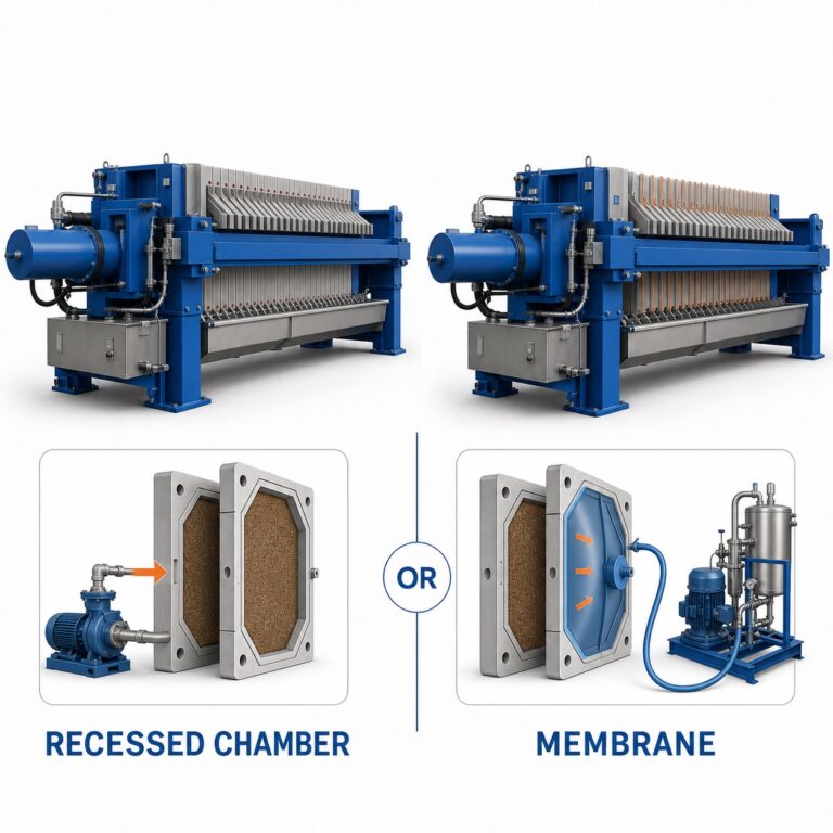
The EPA’s Recessed-Plate Filter Press fact sheet describes the filtrate-removal, plate-chamber, and cake-discharge interfaces common to batch pressure filtration, which is useful background on how these flow paths function mechanically; it does not address open-versus-closed industrial routing choices or project acceptance procedures, so the routing drawing and witnessed check still need to be built around the project’s own specification rather than general reference material. Where the project’s destination map favors visibility for diagnostic comparison between plates, the acceptance check should confirm outlet-level access; where it favors contained routing for environmental or operator-exposure reasons, the check should confirm manifold integrity and isolation points instead. Neither priority is established by the open or closed label on its own, and the acceptance check is what verifies that the equipment actually delivers the arrangement the project selected.
Часто задаваемые вопросы
Q: Can the discharge arrangement be selected before every filtrate destination is defined?
A: No. First map where normal filtrate, samples, reused water, treatment return, off-spec flow, drainage, and spills must go; otherwise, the chosen arrangement may leave a required route or containment boundary unresolved.
Q: Does specifying open discharge guarantee plate-by-plate observation?
A: No. State which outlets operators must see, compare, sample, and reach, then confirm those points against the offered plate and outlet arrangement. The arrangement label alone does not define the observation access.
Q: What should the operations team prepare before requesting quotations?
A: Prepare a short operating brief that names the required observation and sampling tasks, every filtrate destination, any diversion route, and the access operators need at the press. This gives suppliers a concrete basis for showing how their offered arrangement serves each task.
Q: How should the equipment scope be separated from site piping scope for a closed route?
A: Mark the press-side manifold limit and identify the included valves, isolation points, cleanout access, and instruments on the routing drawing. Then identify every connection and pipe section that remains part of the site work so the handoff has no undefined segment.
Q: What should a witnessed flow-path check confirm during acceptance?
A: Use the accepted routing drawing to trace each required path through the actual outlets, manifold, valves, isolation points, and destination connections. The check confirms that the supplied arrangement follows the agreed routing logic; it does not by itself establish an unspecified process-performance result.