How much of the water leaving a tailings thickener and filtration circuit can actually go back into the process, and at what quality? That question cannot be answered by looking at a single machine’s output. It depends on how the site defines its water balance, keeps distinct streams separate, and matches each returned volume to the duty it will serve.
Water Balance Boundaries From Tailings Feed to Reuse
| Balance boundary | Quantity kept distinct | Decision supported |
|---|---|---|
| Tailings feed | Water entering the recovery train | Establishes the inlet side of the site water balance |
| Thickener overflow | Water recovered from thickening | Separates the thickener contribution from filter recovery |
| Filter filtrate | Water recovered from filtration | Separates filter recovery from thickener overflow |
| Return point | Water delivered to the intended reuse duty | Connects recovery to the receiving process rather than a generic recovered-water total |
| Loss | Water within the boundary that is not returned | Reconciles the balance before a recovery value is assigned to any single machine |
A tailings water-recovery circuit only becomes legible once the site agrees on where one quantity ends and the next begins. Feed water entering the thickener, water leaving as thickener overflow, water leaving as filter filtrate, water actually delivered to a return point, and water that is lost within the system are five different quantities. Treating them as one undifferentiated “recovered water” figure makes it impossible to tell which equipment, or which operating change, is responsible for a shift in recovered volume.
The boundary a reader draws changes what a number means. If the boundary is drawn around the thickener alone, overflow volume reflects thickening performance under the feed conditions at that time, and nothing about downstream filtration. If the boundary is drawn around the whole recovery train, the same overflow volume is only one contributor among several, and a change in total recovered water could originate in the feed, the thickener, the filter, or in losses that never reach a return point at all. Neither boundary is wrong; they answer different questions, and confusing them leads to assigning credit or blame to the wrong equipment.
This is why recovery should be quantified by source, by treatment step, by return point, and by loss before any recovery value is assigned to a single machine. A thickener can be operating exactly as designed while total site recovery falls, because losses elsewhere in the circuit, or a change in feed characteristics, are absorbing water that never reaches the balance at all. Conversely, a filter can appear to be underperforming when the real cause is a change in the solids load arriving from upstream, not a change in the filter’s own separation behavior.
For the buyer, the practical consequence is that a water-balance boundary has to be fixed before equipment performance is discussed. Where the project’s interest is comparing thickener contribution against filter contribution, the boundary needs to isolate each stage’s inlet and outlet. Where the interest is overall site water consumption, the boundary needs to extend to every return point and every identified loss. The same tailings circuit supports both questions, but only if the quantities behind each boundary are kept distinct rather than collapsed into a single headline recovery percentage.
Thickener Overflow and Filter Filtrate as Separate Streams
Thickener overflow and filter filtrate are produced by different separation mechanisms, carry different residual solids and chemistry, and arrive at different points in the process timeline. Overflow is produced continuously as settled solids leave the base of the thickener; filtrate is produced as the filter cycles through its own separation and discharge sequence. Even when both streams originate from the same tailings feed, their quality profiles do not move in parallel, because the mechanisms that generate them respond to different operating variables.
Blending the two streams before their quality is understood removes the ability to diagnose either one. If a combined stream shows elevated suspended solids, the site cannot tell without separate data whether the cause lies in thickener settling conditions, in filter cake integrity, or in some interaction between the two once blended. Keeping the streams apart, at least long enough to characterize each one against its own baseline, preserves the diagnostic value of the data and keeps the door open for directing each stream to a different reuse duty if their qualities turn out to differ meaningfully.
The condition that justifies blending is not convenience but demonstrated fit: where both streams meet the same receiving-process requirement and where blending does not obscure a quality excursion that operations would otherwise need to see, combining them can simplify storage and distribution. Where the receiving duties differ, or where one stream carries a quality risk the other does not, blending removes information the site needs for both process control and reuse decisions. The question is not whether overflow and filtrate can physically be combined — they almost always can — but whether the resulting single stream still tells operations what it needs to know and still meets every duty it will be asked to serve.
Reuse Duties and Quality Questions for Each Return Point
| Reuse decision input | Question for each return point | Front de décision |
|---|---|---|
| Stream identity | Is the returned water thickener overflow, filter filtrate, or a blend justified by their quality and end uses? | Determines which stream-specific evidence applies |
| Intended reuse duty | Which receiving process will use the returned water? | Defines the end use against which the stream is assessed |
| Receiving process needs | What water quality does that process need? | A generic clear-water label does not establish fit for the duty |
| Chaîne de traitement | Which treatment steps does the stream pass through before return? | Connects the decision to the water that is actually delivered |
| Applicable site requirements | Which process, chemical, microbial, and regulatory criteria apply? | Acceptance remains project-specific; planning context alone does not establish compliance |
A return point is not validated by the water being visibly clear; it is validated by matching the stream’s actual quality, after whatever treatment steps it has passed through, against the specific requirements of the process that will receive it. Two return points fed by water of identical turbidity can have entirely different acceptance outcomes if one feeds a duty tolerant of suspended solids and the other feeds a duty sensitive to chemistry, particle size, or biological load that turbidity alone does not reveal.
This means the reuse question has to be asked separately for each return point, not once for the recovery circuit as a whole. The first question is which stream is being returned — thickener overflow, filter filtrate, or a blend — because the answer determines which upstream data applies. The second is what process will actually use that water, since a return point feeding dust suppression, process makeup, or wash-down duties carries different implications than one feeding a duty with tighter chemical or particulate tolerance. The third is what that receiving process actually requires, which has to come from the process itself rather than from a general standard for “clean” water.
Le EPA’s water reuse resources frame this as fit-for-purpose planning: matching source water and treatment train to the intended end use and to applicable requirements, rather than applying a single universal reuse threshold. That framing supports the planning conversation, but the specific chemical, microbial, and regulatory criteria that decide whether a given return point is acceptable remain governed by the receiving process and the site’s own applicable requirements, not by the general planning framework.
For the buyer, this translates into a practical discipline: before specifying treatment equipment for a return point, define the receiving duty’s requirements first, then work backward to the treatment train capable of meeting them. Where the receiving duty’s tolerance is wide, a simpler treatment configuration may be adequate; where it is narrow, the treatment train — and the monitoring that confirms it is working — has to be sized to that tighter requirement, not to a generic sense of what counts as reusable water.
Sampling and Monitoring Across the Recovery Train
| Monitoring point | Evidence kept distinct | Operational interpretation |
|---|---|---|
| Tailings feed | Incoming water quantity and quality | Provides the basis for distinguishing feed changes from downstream performance changes |
| Thickener overflow | Overflow quantity and quality | Shows the thickening-stage output without conflating it with filter filtrate |
| Filter filtrate | Filtrate quantity and quality | Shows the filtration-stage output without conflating it with thickener overflow |
| Return point | Quantity and quality delivered to the intended reuse duty | Tests the returned stream against the receiving process needs and applicable site requirements |
| Sampling-program controls | Site, permit, preservation, frequency, and laboratory requirements | These controls remain project-specific when ISO 5667-10 sampling techniques are used |
Distinguishing a feed change from a treatment-stage performance change requires measurements taken at points that do not conflate the two. A single sample taken at the final return point cannot tell the site whether a quality shift originated in the tailings feed, in the thickener, or in the filter, because by the time water reaches that point it carries the combined effect of everything upstream.
Monitoring the feed, the thickener overflow, the filter filtrate, and the return point as separate measurement locations lets operations isolate where a change occurred. If feed quality is stable but overflow quality shifts, the cause sits within the thickening stage. If overflow is stable but filtrate shifts, the cause sits within filtration. If both are stable but the return point shifts, the cause may lie in blending, storage, or an interface between the recovery train and the distribution system. None of these diagnoses are available from a single sampling point.
ISO 5667-10 addresses how a wastewater sampling program should be designed — covering sampling techniques appropriate to the stream being measured — but the site, permit, preservation, frequency, and laboratory requirements that make a sampling program actually usable for this kind of diagnosis remain project-specific decisions the standard does not make on the site’s behalf. Similarly, where suspended solids is the parameter of interest, a method such as Organisation internationale de normalisation 11923 provides a defined way to obtain that result; it establishes a measurement procedure, not a reuse limit or a guarantee that a treatment step is performing adequately.
The practical implication is that a monitoring program built only to confirm a concentration at the final return point meets a reuse requirement — which is a legitimate compliance need — is not the same program needed to manage recovery performance through the thickener and filter stages. A site that wants to attribute changes to a specific stage needs monitoring points positioned to make that attribution possible, not just a compliance check at the point of reuse.
Storage, Blending, and Control Interfaces
Where thickener overflow and filter filtrate are stored before reuse, the storage and blending arrangement becomes a control interface in its own right, separate from the treatment equipment upstream. A storage vessel that receives both streams without separation collapses the distinction the earlier stages worked to preserve, regardless of how carefully overflow and filtrate were monitored individually before they reached that point.
The design question for this interface is whether storage is configured to keep streams segregated until a blending decision is justified, or whether it defaults to combining them on arrival. Segregated storage preserves the option to direct each stream to a different return point and preserves the diagnostic separation established upstream. Combined storage simplifies distribution piping and control logic but commits the site to whichever reuse duty the blended quality can satisfy, and removes the ability to trace a downstream quality issue back to its originating stream.
Control logic at this interface also has to reflect the reuse decision rather than operate independently of it. Where a return point has a defined quality requirement, the control system governing storage and blending needs a basis for knowing when a stream or blend meets that requirement, which depends on the monitoring data from the stages before it. Where that basis is missing, blending becomes a default behavior rather than a decision, and the reuse acceptance question gets answered implicitly by the storage configuration instead of explicitly by the receiving process’s actual needs. Confirming how a proposed configuration handles this interface — whether storage is segregated, blended, or switchable, and what data drives that choice — is a specification question the buyer should raise before equipment layout is finalized, since retrofitting segregation into an already-combined storage arrangement is a different undertaking than specifying it from the outset.
Acceptance Measures for a Stable Water-Return Loop
| Acceptance dimension | Evidence to define or check | What the evidence establishes |
|---|---|---|
| Water-balance closure | Quantified water by source, treatment step, return point, and loss | Reconciles the site balance before recovery is assigned to one machine |
| Overflow and filtrate separation | Separate quantity and quality evidence until blending is justified by quality and intended end uses | Prevents one combined value from concealing stream differences |
| Reuse-duty fit | Receiving process needs and applicable site requirements | Establishes the project-specific basis for accepting water at each return point |
| Feed-versus-stage discrimination | Monitoring comparisons that distinguish feed changes from treatment-stage performance | Supports interpretation of changes across the recovery train |
| Suspended-solids result | A result obtained with a selected method such as ISO 11923:1997 | Provides a measurement; it does not set a reuse limit or guarantee treatment performance |
| Wastewater sampling program | Site, permit, preservation, frequency, and laboratory requirements considered with ISO 5667-10:2020 | Defines project-specific sampling controls; the standard does not establish reuse acceptance by itself |
A water-return loop can be judged stable only against criteria that separate balance closure, stream integrity, reuse fit, and the limits of the evidence used to support each. Conflating these into a single pass or fail judgment hides which part of the loop is actually unresolved.
Balance closure asks whether the quantities entering, moving through, and leaving the recovery train reconcile — feed, thickener overflow, filter filtrate, return-point delivery, and loss accounted for as distinct figures. An unreconciled balance means recovery figures attributed to any one piece of equipment cannot be trusted, regardless of how well that equipment appears to be running in isolation.
Stream integrity asks whether thickener overflow and filter filtrate have been kept distinct long enough to establish that their quality and intended end uses actually justify any blending that occurs. This is a precondition for the next measure, not a substitute for it: streams can be correctly kept separate and still fail to meet their respective reuse duties.
Reuse-duty fit asks whether each return point has been tested against the receiving process’s actual requirements and the site’s applicable requirements, rather than against a general sense of acceptable water quality. This is where the EPA’s fit-for-purpose framing applies as planning context, while the specific criteria that decide acceptance remain project-specific.
Feed-versus-stage discrimination asks whether the monitoring program in place can actually distinguish a feed-driven change from a treatment-stage change, which depends on whether sampling points were positioned for that purpose rather than only for a single compliance check.
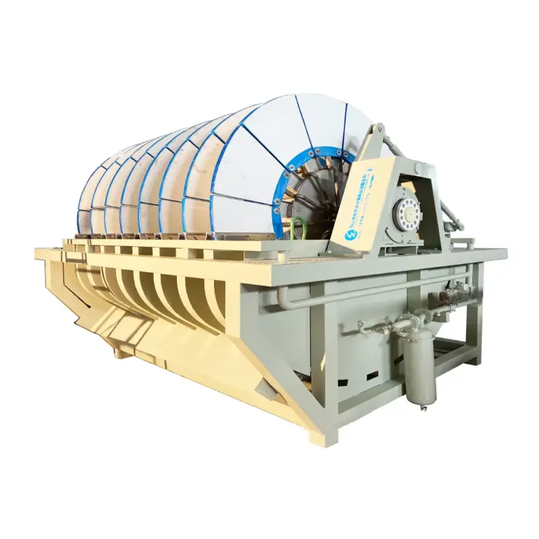
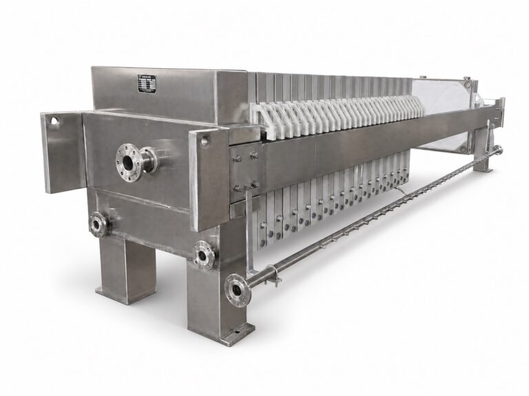
Finally, the measurement evidence itself has defined limits. A suspended-solids result obtained through a method such as ISO 11923 is a measurement, not a reuse limit. A sampling program built with ISO 5667-10’s techniques still depends on project-specific site, permit, preservation, frequency, and laboratory decisions to be meaningful. Where a buyer is assembling the operating and site information needed to evaluate equipment such as a filtre à disque céramique sous vide ou un filtre-presse à membrane for the filtration step, or reviewing systèmes de traitement des eaux usées for the train as a whole, this is the information Porvoo’s configuration and quotation review would need: the balance figures by boundary, the separated stream data, the return-point requirements, and the monitoring arrangement already in place or planned, rather than a single recovery percentage presented without its supporting boundaries.
Questions fréquemment posées
Q : Can thickener overflow and filter filtrate be reported as one recovered-water stream?
A : Only after separate quantity and quality evidence shows that blending is suitable for the intended reuse duty. Until then, track the streams separately so their contributions and differences are not hidden in one total.
Q : What should be defined before assigning a water-recovery value to a filter or thickener?
A : Define the balance boundary and quantify water entering with the tailings feed, leaving through each recovery stage, reaching each return point, and remaining as loss. Reconcile those quantities before attributing recovery to any single machine.
Q : Is visually clear recovered water ready for process reuse?
A : Visual clarity alone does not establish reuse suitability. Identify the receiving process, its water-quality needs, and the applicable site-specific process, chemical, microbial, and regulatory criteria, then assess the water actually delivered to that return point.
Q : How can operators tell whether a change comes from the feed or from a treatment stage?
A : Keep quantity and quality results distinct at the tailings feed, thickener overflow, filter filtrate, and return point. Comparing those locations under a consistent sampling program lets the team check whether the change was already present upstream or appeared across a treatment stage.
Q : What should be agreed before a monitoring program begins?
A : Set the sampling locations, frequency, preservation, laboratory requirements, and the criteria tied to each reuse duty. Methods such as ISO 11923 and ISO 5667-10 can support measurement and sampling design, but they do not set a reuse limit or prove that a treatment result is acceptable for the site.