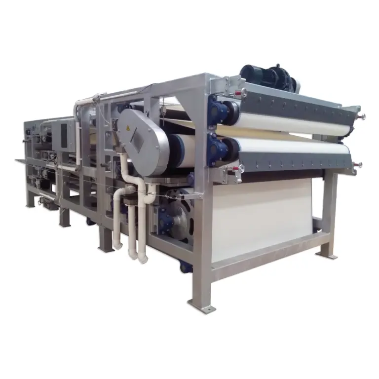
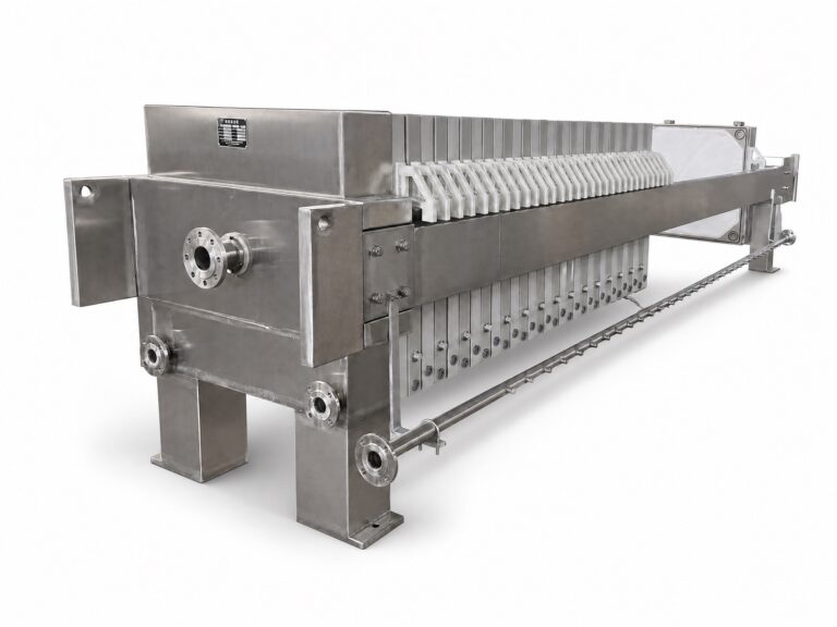
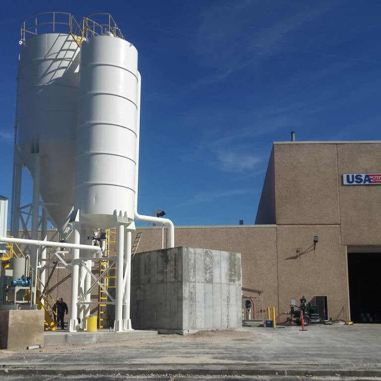
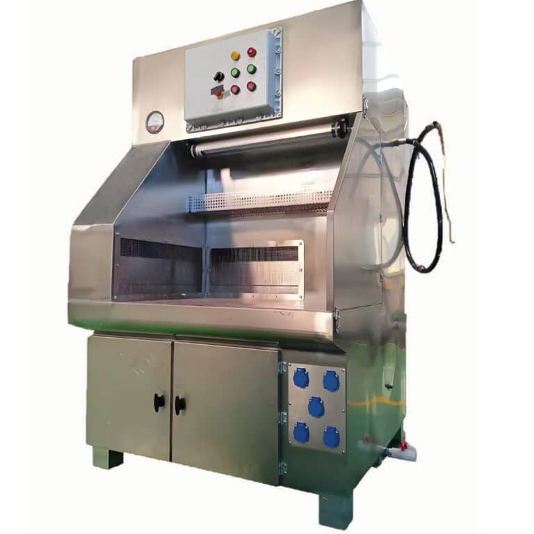
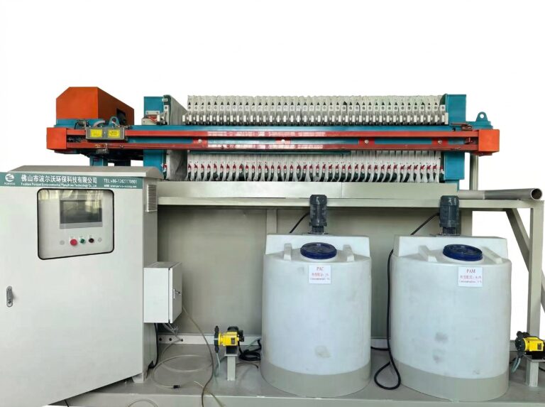
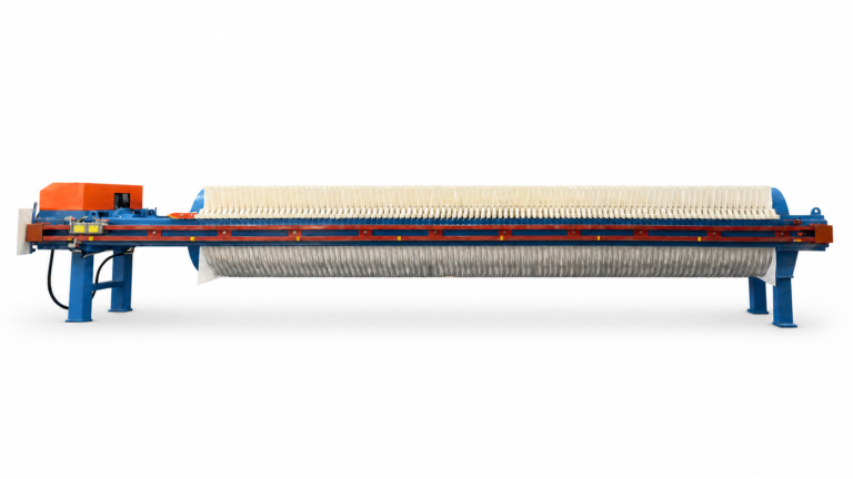
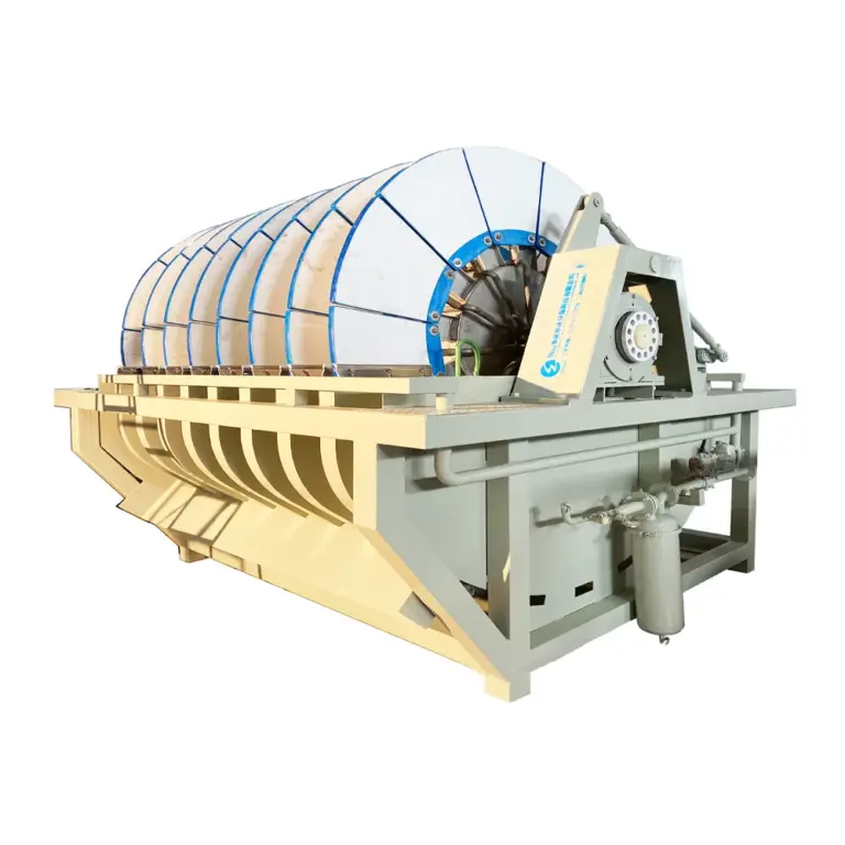
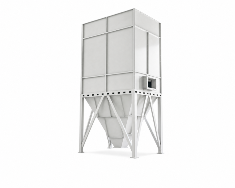
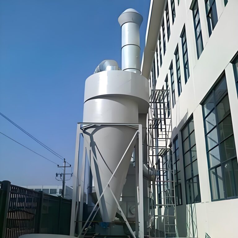
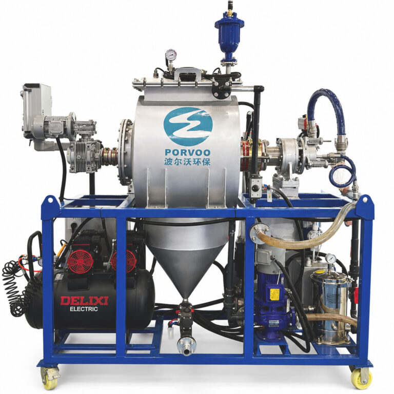
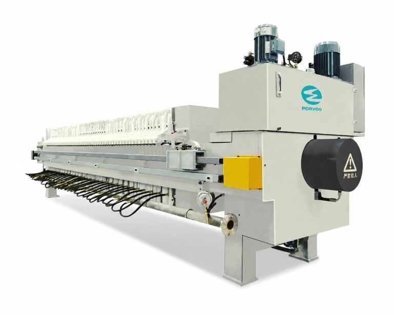
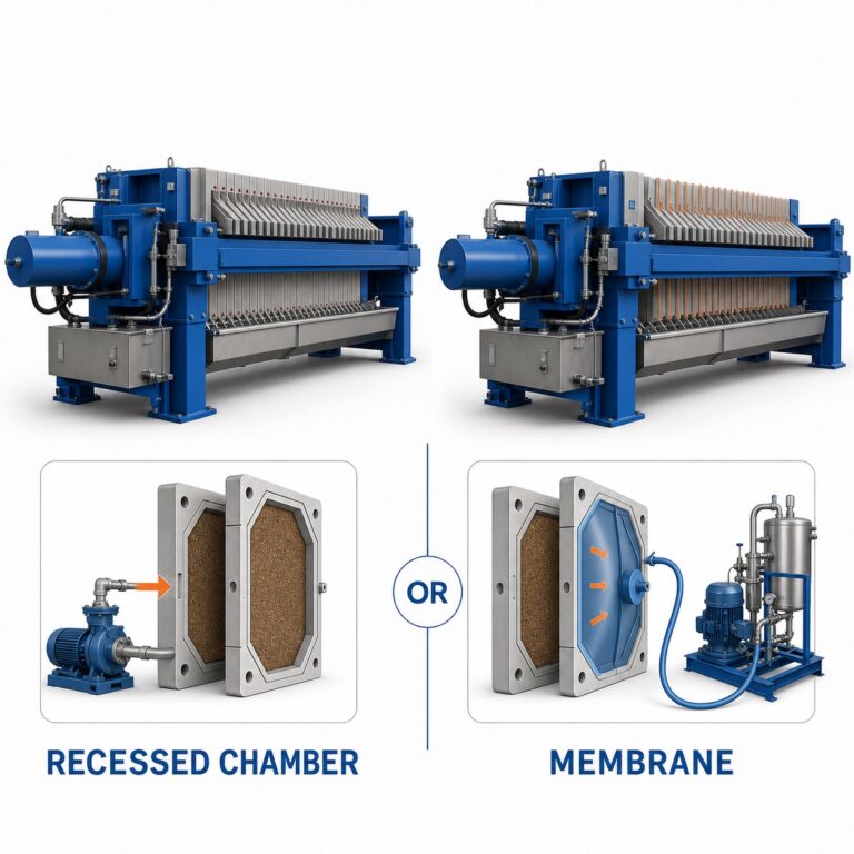
A filtre-presse à chambres en retrait arrives as a configured piece of equipment, not a self-contained package. Whether it performs, integrates, and holds up to maintenance depends on interfaces the supplier does not control directly: civil supports, piping tie-ins, cable routes, access for plate and cloth work, and the path the discharged cake takes once it leaves the machine. The question a buyer needs to answer before layout release is not whether the press is correctly sized, but whether every physical and procedural interface around it has been defined, assigned, and checked.
Site information the supplier needs before layout release
| Site input | Information to record before layout release |
|---|---|
| Equipment limits and support points | Show the equipment boundary and support locations on the interface drawing. |
| Feed, filtrate, and drain interfaces | Show the connection points and drains that the site layout must accommodate. |
| Services publics | List every utility in the quoted configuration with its supplier, connection point, operating basis, and owner. |
| Service access | Reserve access for plate movement, cloth work, cleaning, inspection, and cake collection. |
| Lifting or removal access | Identify any lifting or removal task required by the supplied configuration and reserve the necessary access. |
| Evacuation du gâteau | Show the destination of discharged cake and the site collection interface. |
Layout release depends on information the site holds and the supplier does not generate independently. The equipment boundary, support locations, feed and filtrate connections, and drains all need to be fixed on one interface drawing before civil and piping work can proceed with confidence. Where this drawing is incomplete or assumed rather than confirmed, layout decisions made early get revisited later, once the real site conditions surface.
A central distinction is between what the supplier’s quoted configuration contains and what the site assumes a chamber press requires by default. Utilities are not a fixed list across projects: the configuration PORVOO or any supplier provides for one application may draw compressed air, hydraulic power, or control power from different points than another configuration drawing on different feed solids or cake requirements. For each utility actually in the quoted scope, the supplier, connection point, operating basis, and owner need to be recorded individually rather than inferred from a prior project or a generic press layout.
Access is a second category of input that changes with the supplied configuration. Plate movement, cloth work, cleaning, inspection, and cake collection each require their own reserved space, and the configuration determines how much space each activity needs and where it sits relative to the equipment footprint. If the supplied configuration also includes a lifting or removal task — moving a component in or out for service, for example — that task has its own access requirement that must be identified from the configuration itself, not assumed from the base equipment outline.
Where the destination of the discharged cake has not been fixed, downstream decisions about site collection, conveyance, or storage cannot be checked against the equipment’s actual discharge interface. This is where the information gap most directly shows up during layout: a press can be specified correctly and still interface poorly with a site if the cake destination and the collection method on the receiving end were never agreed.
This is the stage where project information most directly enters a supplier’s configuration or quotation review: dimensions, support locations, utility points, and access constraints submitted by the site shape how the equipment is arranged and which auxiliary items the quoted configuration includes.
Civil supports, footprint, access, and lifting interfaces
| Interface | Project detail to check | Approval question |
|---|---|---|
| Support points | Support locations shown on the interface drawing | Does the civil provision match the documented support interface? |
| Equipment footprint | Equipment limits and installed area for the supplied configuration | Does the allocated area accommodate the documented equipment limits? |
| Plate and cloth work access | Space reserved for plate movement and cloth work | Can the identified plate and cloth tasks be performed within the reserved access? |
| Cleaning and inspection access | Space reserved for cleaning and inspection | Is the documented access available for both activities? |
| Lifting or removal access | Access for each lifting or removal task identified for the supplied configuration | Has the required route or working space been reserved? |
Civil and access provisions are judged against the documented interface, not against a generic footprint assumption. Support points carry the equipment’s operating loads, and where those loads or their locations differ from what civil work has prepared for, the mismatch surfaces only when equipment arrives — a point at which civil correction is far less convenient than it would have been during design. Confirming that civil provision matches the documented support interface, rather than a nominal footprint, is therefore a distinct check from confirming that the allocated area is large enough.
Footprint and access serve different purposes even though both concern physical space. Footprint confirms that the equipment fits; access confirms that people and components can move around it during operation and maintenance. A site can satisfy the footprint requirement while failing the access requirement, particularly where nearby structures, other equipment, or walkways encroach on the clearance that plate movement or cloth work needs. Because plate movement and cloth work happen on a recurring basis as part of operating the press, access reserved only as unused floor area — without clear routes and working clearances — does not meet the same interface requirement as space reserved for routine cleaning or inspection, where the activity profile differs.
Lifting or removal access deserves separate attention because it is tied to the supplied configuration rather than to the press category as a whole. Where a configuration includes a component intended for periodic removal or a task requiring overhead lifting, the route and working space for that task need to be reserved specifically, informed by what the configuration actually requires rather than by a standard clearance figure. A civil layout adequate for one configuration’s lifting needs may be inadequate for another’s, even where the base equipment looks similar. The EPA’s fact sheet on recessed-plate filter presses, describing the installed support, area, and regular operating-attention interfaces associated with this equipment class, is a useful general reference for the kinds of interfaces involved — though it addresses biosolids-route mechanics in a municipal context, and industrial site dimensions, utilities, and supplier scope still require confirmation against the specific project.
Feed, filtrate, drainage, and cake-handling connections
| Connection path | Interface detail to confirm | Site check |
|---|---|---|
| Flux | Feed connection and feed-pump interface for the supplied configuration | Confirm that the site feed route reaches the documented equipment connection. |
| Filtrat | Filtrate connection and removal interface | Confirm that the planned filtrate route matches the documented connection. |
| Drainage | Drain connections shown on the interface drawing | Confirm that site drainage work covers each documented drain interface. |
| Evacuation du gâteau | Discharge point, cake destination, and collection interface | Confirm that the site cake-handling arrangement serves the documented discharge destination. |
Feed, filtrate, drainage, and cake discharge are four separate connection paths, each with its own routing logic and its own failure mode if left unconfirmed. Treating them as a single “piping scope” risks leaving one path unexamined while the others receive attention.
The feed connection interfaces with a feed pump, and the route from the site’s feed source to the documented equipment connection needs to match what the interface drawing specifies — not only in terms of endpoint location but also in terms of how the feed line approaches the press. Filtrate removal is a separate path with its own connection point; because filtrate leaves the press under different conditions than feed enters it, the two paths are rarely interchangeable in routing logic even where they terminate near each other physically.
Drainage differs from both in purpose: drain connections shown on the interface drawing exist to handle conditions distinct from normal process flow, and site drainage work needs to address each documented drain point individually rather than assuming a single site drain covers the equipment’s needs. Where a project’s drainage provision was planned before the interface drawing was finalized, a mismatch between planned and documented drains is a common point of rework.
Cake discharge is the path most directly tied to what happens after the press completes its function, and it connects back to the destination and collection interface established during layout. Confirming that the site’s cake-handling arrangement actually serves the documented discharge destination — rather than assuming collection equipment can be positioned wherever convenient after the fact — closes the loop between the layout-stage decision about cake destination and the physical reality of the installed site. Where the discharge interface changes between quotation and final configuration, this connection path is the one most likely to require a second look, since it sits at the boundary between the equipment’s documented limits and the site’s downstream handling.
Utilities, controls, instruments, and responsibility boundaries
| Work package | Boundary to record |
|---|---|
| Services publics | For each utility in the quoted configuration, record the supplier, connection point, operating basis, and owner. |
| Piping and valves | Name the party responsible for piping and valves at the documented equipment connections. |
| Instruments and controls | Name the party responsible for the instruments and controls at the equipment boundary. |
| Electrical work and cable routes | Show the cable routes and connection points, and name the party responsible for the electrical work. |
| Travaux de génie civil | Name the party responsible for the documented support and footprint interfaces. |
| Guarding and platforms | Name the party responsible for the guarding and platform work included at the site interface. |
| Drainage | Name the party responsible for each documented drain connection. |
| Commissioning support | Name the party providing commissioning support and tie that support to the contract scope. |
Interfaces are physical; responsibility boundaries are organizational. A site can have every physical connection correctly placed and still face delays or disputes if no party has been named as responsible for completing or verifying that connection. This section addresses a different kind of readiness than the two preceding it: not whether an interface exists, but who installs, connects, and owns it.
Utilities again require individual treatment rather than bulk assumption. Each utility within the quoted configuration carries its own supplier, connection point, operating basis, and owner, and recording these separately avoids the situation where one utility’s readiness is confirmed while another, assumed to be bundled with it, is not. Piping and valves at the documented equipment connections need a named responsible party distinct from the party responsible for instruments and controls at the equipment boundary — these are frequently different trades with different schedules, and an interface drawing that shows the connection without assigning the work leaves the scheduling question open.
Electrical work follows a similar logic: cable routes and connection points need to be shown, and the party responsible for the electrical work needs to be named against those specific routes rather than against a general electrical scope. Civil work, guarding, platforms, and drainage each carry their own responsible party in the same way, because each is a distinct trade with its own sequencing relative to equipment delivery.
Commissioning support is the responsibility boundary most directly tied to the contract itself. Naming the party providing commissioning support only has meaning when that support is tied back to the contract scope — otherwise “commissioning support” can mean different things to the site and the supplier, discovered only once commissioning begins. Where the project information submitted earlier shapes equipment configuration, the responsibility matrix is the counterpart that shapes installation coordination: it determines which party acts on each documented interface rather than what the interface itself requires.
Risk-review actions for operation, cleaning, and maintenance
A recessed-chamber press presents hazards connected to its normal functions — plate movement, cloth work, cleaning, and maintenance access among them — and a risk review for these functions follows a general framework rather than a fixed checklist specific to one site. ISO 12100:2010 describes this framework at the level of hazard identification, risk estimation and evaluation, risk reduction, and documentation, and it applies as a general machinery-safety method rather than as proof that any particular equipment or supplier configuration already meets its requirements. Where a project team applies that framework to a specific installation, the review needs to work through the press’s actual operating, cleaning, and maintenance activities as configured for that site, rather than treating the framework itself as the completed review.
The distinction that matters here is between having a risk-review framework in place and having closed the actions that framework identifies. A framework establishes how hazards connected to plate movement, cloth work, and access are to be identified and evaluated; it does not by itself establish that any specific hazard connected to this press, at this site, has been addressed. Where the access and interface decisions made earlier — reserved space for cloth work, lifting routes, drainage near cleaning areas — were defined without reference to the risk review, the review may surface conflicts between what was physically reserved and what the hazard evaluation calls for. Closing these conflicts before equipment arrives is less disruptive than closing them afterward, since physical access and civil provisions are harder to adjust once built.
Risk-review actions connected to operation concern the ongoing interaction between operators and the press during normal cycles; those connected to cleaning concern the recurring access and exposure involved in cloth work and chamber access; those connected to maintenance concern less frequent but potentially more involved interventions, including any lifting or removal task the configuration requires. Each of these activity areas can generate its own set of review actions, and treating them as one undifferentiated “safety review” risks under-addressing whichever activity received less attention during the review process. A documented review that specifically addresses all three — operation, cleaning, and maintenance — as they apply to the supplied configuration is the standard the project team can reasonably hold itself to, using the general risk-assessment method as the structure rather than as the content.
Interface sign-off before shipment and site commissioning
| Sign-off item | Éléments à examiner | Front de décision |
|---|---|---|
| Approved interface drawing | Approved drawing showing equipment limits, support points, connections, drains, cable routes, controls, and the cake destination | Confirms that the project interface definition is approved for release. |
| Risk-review actions | Record showing closure of the applicable project risk-review actions | Confirms closure under the project review; it does not by itself establish equipment or supplier compliance. |
| Utility availability | Confirmation for every utility listed in the quoted configuration, including its connection point and operating basis | Confirms availability against the quoted project configuration. |
| Access checks | Documented check covering plate movement, cloth work, cleaning, inspection, cake collection, and identified lifting or removal tasks | Confirms that the required access has been reserved for the supplied configuration. |
| Handover plan | Documented handover plan tied to the contract scope and the named commissioning support | Confirms the agreed handover boundary for site commissioning. |
Sign-off is the point where the interfaces defined earlier are checked against what has actually been achieved on site, before equipment ships and before commissioning begins. This section is not about defining new interfaces; it is about confirming that the interfaces already established have been met, and distinguishing confirmation from assumption.
The approved interface drawing is the reference point for this check: it shows equipment limits, support points, connections, drains, cable routes, controls, and the cake destination, and sign-off confirms that this definition has been approved for release — not that every item on it has necessarily been built yet, but that the definition itself is settled. Risk-review actions are checked separately, and their closure confirms closure under the project review specifically; it does not, on its own, establish that the equipment or supplier configuration complies with any broader standard, a distinction worth holding onto since the two are sometimes conflated.
Utility availability is checked against the quoted configuration rather than against a general expectation of what utilities a press needs — each utility listed needs its connection point and operating basis confirmed individually. Access checks cover the same activities identified earlier: plate movement, cloth work, cleaning, inspection, cake collection, and any lifting or removal task specific to the configuration, and confirming these at sign-off closes the loop between what was reserved during civil planning and what is actually usable once installation is complete.
Le handover plan is the final element, and it ties commissioning support back to the contract scope — the same boundary established earlier when responsibility was assigned. A handover plan that does not reference the contract scope leaves open exactly how much support the commissioning phase includes, which is the same ambiguity the responsibility matrix was meant to resolve earlier in the project. Where all of these items are confirmed together — drawing, risk-review closure, utility availability, access, and handover plan — the project has a documented basis for proceeding to shipment and commissioning; where any one is missing, that specific gap, not a general readiness judgment, is what the project team still needs to resolve before commissioning can begin on the terms the contract describes.
Questions fréquemment posées
Q : Can the civil and utility plan from another recessed-chamber press project be reused?
A : Use it only as a starting reference. Release this project’s layout against the supplied configuration and its approved interface drawing, because support locations, connections, access needs, and the auxiliary package may differ. Recheck each of those items before committing site work.
Q : What should the project team do when equipment supply and site scope appear to overlap?
A : Treat the overlap as unresolved until the equipment boundary and one named owner for the work package are documented. Make the same responsibility split visible in the interface drawing, contract scope, and handover plan so installation and commissioning teams work from one agreed boundary.
Q : Does a configuration change require the site-readiness review to be repeated?
A : Recheck every interface affected by the change and any dependent sign-off. Compare the revised configuration with the utility list, operating bases, connection points, supports, access provisions, cake route, and assigned responsibilities; do not rely on the earlier approval until the drawing and checks agree again.
Q : How can the team tell whether the cake-handling arrangement fits the installation layout?
A : Trace the full path from the documented discharge point to the collection interface and final cake destination. Check that this path fits the site plan without consuming the access reserved for plate movement, cloth work, cleaning, inspection, or any identified lifting and removal task.
Q : Does approval of the interface drawing establish machinery safety or supplier compliance?
A : No. It confirms that the project interface definition is approved for release. The project must still close its applicable risk-review actions for operation, cleaning, and maintenance; that closure records the project review and does not by itself prove equipment or supplier compliance.