Las instalaciones que omiten la eliminación temprana de sólidos o la realizan a una escala insuficiente a menudo no se dan cuenta del coste hasta que las bombas empiezan a desgastarse más rápido de lo esperado y el consumo de reactivos aumenta sin una explicación clara. Para cuando el patrón se hace visible, ya se ha agravado en todas las etapas posteriores: mayor demanda de productos químicos, sedimentación inestable, humedad del lodo inconsistente y un tanque de reutilización que nunca se mantiene del todo dentro de los límites de calidad. La decisión que evita la mayor parte de esto no es la elección de un único equipo, sino una valoración de la secuencia: confirmar que cada etapa de tratamiento está dimensionada para la carga que realmente recibirá, incluyendo los picos de caudal y las condiciones de sobrecarga, antes de que el sistema entre en funcionamiento. Los lectores que analicen este proceso desde la entrada hasta el tanque de reutilización estarán en mejores condiciones para identificar dónde su diseño actual o previsto conlleva un coste oculto.
Empecemos por las fuentes de aguas residuales de cerámica y la variación del caudal
La producción de baldosas cerámicas genera aguas residuales procedentes de múltiples puntos simultáneamente —molienda en húmedo, líneas de pulido, preparación de esmaltes y lavado de equipos— y cada fuente presenta una concentración de sólidos, una distribución del tamaño de las partículas y un caudal diferentes. El problema no es que estos flujos sean difíciles de tratar individualmente, sino que llegan en momentos distintos y con intensidades diferentes durante un turno de producción. Sin una gestión deliberada del caudal en la entrada, un sistema de sedimentación o dosificación dimensionado para condiciones medias se verá periódicamente sobrecargado y periódicamente infrautilizado, situaciones que no gestiona bien.
Un tanque de compensación con agitación mecánica continua resuelve ambos problemas a la vez. Absorbe los picos de corta duración que se producen cuando varias áreas de producción descargan simultáneamente, y la agitación evita que las partículas gruesas se depositen de forma desigual en el fondo del tanque, lo que de otro modo crearía una zona muerta que periódicamente desprendería sólidos concentrados hacia la línea de alimentación. La consecuencia práctica de omitir la agitación —o de utilizar un tanque lo suficientemente grande como para igualar el caudal, pero no equipado para mantener los sólidos en suspensión— es que la composición de la alimentación que llega a la etapa de eliminación de arena varía de forma impredecible. Esas variaciones son las que convierten un sistema aguas abajo correctamente dimensionado en uno que parece estar infradimensionado.
Para llevar a cabo esta etapa correctamente, lo importante no es tanto la especificación del tanque de compensación en sí misma, sino más bien darse cuenta de que cualquier irregularidad en las fases previas que llegue a las etapas de dosificación química y sedimentación supondrá un coste mayor de corrección allí de lo que habría costado prevenirla aquí.
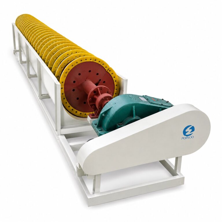
Elimine las partículas de gran tamaño antes del tratamiento químico
El rango de tamaño de partículas que con mayor frecuencia causa problemas en las etapas posteriores del tratamiento de las aguas residuales procedentes de la fabricación de baldosas cerámicas es la fracción más gruesa —aproximadamente entre 300 y 500 mesh— y no la arcilla coloidal fina para cuya eliminación está diseñada la dosificación de productos químicos. Las partículas de este rango son lo suficientemente pesadas como para sedimentarse rápidamente en zonas de baja velocidad, lo que significa que se acumulan en los codos de las tuberías, los cuerpos de las válvulas y las carcasas de las bombas, en lugar de llegar al tanque de tratamiento, donde podrían eliminarse de forma intencionada. También son lo suficientemente gruesas como para causar un desgaste abrasivo en los impulsores y las juntas que, aunque no es lo suficientemente grave como para provocar un fallo inmediato, sí es lo suficientemente constante como para acortar la vida útil de todo el sistema posterior.
Esta es la etapa que con mayor frecuencia se subestima u omite durante la fase inicial de diseño del sistema, en parte porque su valor no es apreciable cuando el sistema es nuevo. La eliminación de sedimentos no mejora visiblemente la calidad del agua como lo hace la clarificación, y su ausencia no se percibe inmediatamente como un problema de calidad del agua, sino que se manifiesta como un problema de mantenimiento varios meses después de la puesta en marcha. El argumento financiero a favor de desarenado de partículas grandes Por lo tanto, se trata de una cuestión de costes de mantenimiento y reactivos, no solo de calidad del agua: la eliminación de las partículas abrasivas antes del acondicionamiento químico reduce el desgaste de las bombas dosificadoras y los mezcladores, y disminuye la cantidad de coagulante que, de otro modo, sería necesaria para capturar partículas que el PAC y el PAM no están diseñados para aglomerar de manera eficaz.
Si se está considerando la eliminación de arena como una adaptación posterior y no como un elemento del diseño original, la secuencia de instalación es importante. Añadirla una vez que el sistema de dosificación ya está en funcionamiento significa que el sistema se ha ajustado para compensar la carga de partículas gruesas, y ese ajuste deberá revisarse una vez que se elimine dicha carga. Prevea un periodo de reoptimización en lugar de dar por sentado que las tasas de dosificación se mantendrán sin cambios.
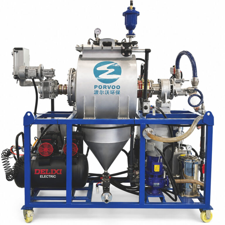
Utilice la dosificación de PAM/PAC para formar flóculos sedimentables
La dosificación de productos químicos es el aspecto del sistema de tratamiento que más contribuye a su rendimiento de clarificación, y también es donde se cometen los errores de ajuste más habituales. El PAC (cloruro de polialuminio) actúa como coagulante, desestabilizando las partículas cargadas de arcilla y pigmentos que permanecen en suspensión tras la eliminación de la arena. El PAM (poliacrilamida) actúa como floculante, uniendo las partículas desestabilizadas en agregados más grandes y pesados que se sedimentan dentro del tiempo de residencia disponible en el clarificador. Si se utilizan juntos y se dosifican correctamente, producen flóculos que se separan de forma predecible. Si se dosifican incorrectamente —o se ajustan solo a condiciones de caudal medio—, producen flóculos que funcionan durante el funcionamiento estable y se desintegran ante picos de caudal.
Es importante comprender con precisión el problema de los picos de caudal. Cuando el caudal aumenta bruscamente, el tiempo de residencia hidráulica en la zona de mezcla disminuye, lo que reduce el tiempo de contacto entre el coagulante y las partículas. Al mismo tiempo, cambia la turbulencia en la cámara de mezcla, lo que afecta al crecimiento de los flóculos. Un sistema de dosificación ajustado a condiciones medias dosificará de forma insuficiente durante los picos, produciendo flóculos débiles que pasan a la etapa de sedimentación como sólidos no sedimentables. Esos sólidos no desaparecen: se acumulan en el flujo inferior del clarificador, aparecen en el filtrado y, finalmente, llegan al tanque de reutilización. Las instalaciones que utilizan un sistema de dosificación proporcional al caudal o automatizado —uno que ajusta las dosis de reactivo en respuesta al caudal entrante y a la turbidez— gestionan los picos de caudal significativamente mejor que aquellas que utilizan bombas peristálticas de caudal fijo. Un sistema inteligente de dosificación de productos químicos que monitoriza las variaciones en el caudal y ajusta las dosis de PAC y PAM en consecuencia, evita el colapso de los flóculos que la dosificación a dosis fija no puede evitar durante los picos de producción.
Una condición que a menudo se pasa por alto es la interacción entre la dosis de PAC y el pH. El rendimiento del PAC es sensible al rango de pH de funcionamiento; fuera de ese rango, la eficacia de la coagulación disminuye y el exceso de aluminio puede pasar al efluente del clarificador. Si el pH del agua de entrada varía —lo cual ocurre a menudo en las fábricas de azulejos que procesan esmaltes con composiciones químicas diferentes—, la optimización de la dosificación debe incluir la monitorización del pH en la etapa de acondicionamiento, y no solo en la salida.
Depura el agua antes de que llegue al depósito de reutilización
La sedimentación elimina la fracción sedimentable de la carga de flóculos, pero no lo elimina todo. Las partículas finas que no fueron capturadas en la etapa de coagulación-floculación, así como el material coloidal residual que sobrevivió a la fase de dosificación, permanecen en suspensión en el rebosadero del clarificador. Si este rebosado se vierte directamente en el tanque de reutilización, la fracción no sedimentable se acumula con el tiempo y eleva el nivel de referencia de la calidad del agua reciclada hasta que empieza a afectar a la producción, sobre todo en el esmaltado y el acabado de superficies, donde la calidad del agua influye en la consistencia del producto.
El pulido tras la sedimentación aborda este problema de forma directa. La filtración multimedia elimina los sólidos en suspensión no sedimentables que la clarificación no puede capturar, y una configuración de la bolsa filtrante adecuadamente seleccionada —que utilice un distribuidor de agua recíproco— evita la acumulación desigual de sedimentos en el interior de la bolsa, lo que acorta su vida útil y provoca que la caída de presión aumente más rápido de lo esperado. La medición de la turbidez en la salida del clarificador, tomando como referencia la norma ISO 7027-1:2016 como marco de ensayo pertinente para la claridad del agua, ofrece una forma práctica de confirmar si la etapa de pulido mantiene el nivel de calidad que requiere el depósito de reutilización.
| Equipamiento | Función | Por qué es importante |
|---|---|---|
| Filtración multimedia | Elimina los sólidos en suspensión no sedimentables tras la sedimentación | Garantiza que el agua tratada cumpla con los estándares de reutilización |
| Saco filtrante con distribuidor de agua de movimiento alternativo | Evita la acumulación de sedimentos en el interior de la bolsa y prolonga su vida útil | Mejora la fiabilidad de la filtración y reduce las interrupciones por mantenimiento |
En la fase de diseño, a menudo se subestima la repercusión que esto tiene en el mantenimiento. Una bolsa filtrante que no esté equipada con un distribuidor recíproco tiende a desarrollar «canalización»: el flujo se concentra por la vía de menor resistencia, eludiendo las zonas donde se han acumulado sedimentos, lo que significa que el área de filtración se utiliza de forma ineficiente y que los intervalos de mantenimiento se acortan con respecto a lo indicado en las especificaciones. Se trata de un coste de mantenimiento que se refleja en las operaciones, no en la comparación de costes de capital, por lo que suele pasar desapercibido durante la adquisición.
Deshidratar los lodos sin desestabilizar el circuito de reciclaje
La gestión de los lodos es el ámbito en el que el ciclo de reciclaje se ve desestabilizado con mayor frecuencia, sin que ello active ninguna alarma evidente. La relación entre el rendimiento del desaguado y la calidad de la producción es indirecta —pasa por el contenido de humedad de la torta de filtración y su efecto en la mezcla de materias primas—, lo que significa que el origen de un cambio en la producción rara vez se identifica como un problema del sistema de agua hasta que ya se ha llevado a cabo una investigación exhaustiva.
El mecanismo es sencillo: si la prensa de filtro recibe lodos con una carga de sólidos irregular —lo que ocurre cuando la extracción del clarificador no se sincroniza correctamente o cuando se deja que se acumule la capa de lodos y luego se descargue en grandes lotes—, la torta de filtración resultante tendrá un contenido de humedad variable. Cuando esa torta se reintroduce en la preparación de la materia prima, como es habitual en las plantas de baldosas que intentan un funcionamiento con vertido cero, la humedad irregular altera la proporción de la mezcla. La línea de producción no recibe una señal de que el sistema de agua haya causado el problema; recibe una variación en la calidad del producto que parece un problema de materiales.
La asistencia por vacío en el depósito receptor acelera el paso del agua a través de la bolsa filtrante y mejora el grado de secado de los lodos, lo que reduce la duración del ciclo y permite obtener una torta con un contenido de humedad más uniforme. La medición del contenido de agua de la torta de filtración antes de que se devuelva a la mezcla de materia prima convierte lo que, de otro modo, sería una variable incontrolada en una variable controlada.
| Medida | Mecanismo | Acto benéfico a favor de Recycle Loop |
|---|---|---|
| Asistencia por vacío en el depósito receptor | Acelera el paso del agua a través de la bolsa filtrante | Reduce la duración del ciclo de deshidratación y aumenta el grado de secado de los lodos |
| Medición del contenido de agua de la torta de filtración | Permite una reintroducción controlada en la mezcla de materias primas | Evita problemas en el procesamiento al garantizar un contenido de humedad constante |
El momento en que se retira el lodo del clarificador también es más importante de lo que suele pensarse. Dejar que se acumule la capa de lodo antes de retirarla reduce la concentración de sólidos en el flujo de fondo del clarificador, lo que significa que el filtro prensa recibe una suspensión más diluida y necesita más ciclos para procesar la misma masa de sólidos. Una extracción controlada y más frecuente mantiene un flujo de salida más espeso, reduce el número de ciclos del filtro prensa y produce una torta más homogénea, lo que en conjunto reduce la variabilidad introducida en el flujo de materia prima.
Para obtener una visión más detallada de cómo interactúan la sedimentación y el tratamiento de lodos en entornos industriales con alto contenido de sólidos, véase el análisis de la secuencia en procesos de tratamiento de aguas residuales para fábricas con un alto contenido de sólidos aborda directamente esta interdependencia.
Selecciona el filtrado en función de la calidad, no de la comodidad
La decisión predeterminada sobre el recorrido —devolver el filtrado al inicio del proceso independientemente de su calidad— es sencilla desde el punto de vista operativo, pero incorrecta desde el punto de vista analítico. El filtrado del filtro prensa contiene sólidos suspendidos residuales y, si la etapa de deshidratación ha estado procesando lodos procedentes de una etapa de coagulación que utiliza coagulantes a base de aluminio, también puede contener trazas de metales disueltos. La norma ISO 11923:1997 proporciona el marco de ensayo pertinente para medir los sólidos en suspensión en el filtrado y determinar si la calidad medida justifica el retorno al inicio del proceso o requiere una ruta de distribución diferente. Sin medirlo, la decisión sobre la distribución se toma por suposición, no por una calidad confirmada.
| Medida | Propósito | Ventaja operativa |
|---|---|---|
| Sifón en un tubo de líquido transparente | Mantiene el vacío y evita la entrada de aire | Garantiza una calidad constante y óptima del filtrado sin interrupciones |
| Filtración por membrana para la eliminación de metales | Se aplica cuando los requisitos de calidad de las aguas residuales superan los del tratamiento estándar | Permite un enrutamiento basado en la calidad sin comprometer el ciclo general de reutilización |
La elección entre el retorno de filtrado estándar y la filtración por membrana es una decisión basada en el coste y la calidad, no una especificación válida para todos los casos. La filtración por membrana implica un mayor coste de inversión y una mayor complejidad operativa, pero ofrece una capacidad de eliminación de metales que la filtración estándar no puede proporcionar. En las instalaciones donde el agua reutilizada entra en contacto con las superficies de los productos o se introduce en sistemas de pulverización en los que los metales disueltos podrían causar defectos, los requisitos de calidad justifican este paso adicional. En las instalaciones en las que la calidad del filtrado procedente de una prensa bien operada cumple sistemáticamente la norma de reutilización, basta con un sifón de tubería —correctamente instalado para mantener el vacío y evitar la entrada de aire—. El error no es elegir la opción más sencilla, sino elegirla sin confirmar primero que dicha opción cumple realmente el umbral de calidad que exige el depósito de reutilización.
El filtrado que se recircula con niveles elevados de sólidos en suspensión o metales no provoca una crisis inmediata. Provoca un cambio gradual en los valores de referencia del agua de recirculación, lo cual resulta más difícil de detectar y de rastrear hasta su origen una vez que se ha acumulado a lo largo de múltiples ciclos de recirculación. Por lo tanto, el enrutamiento basado en la calidad no es principalmente una decisión de control de calidad, sino una decisión de estabilidad del sistema.
Comprueba el equilibrio del proceso en condiciones normales de carga de producción
Un balance hídrico que parece correcto sobre el papel puede no ser válido en condiciones reales de producción. La diferencia entre un balance de masas teórico y uno operativo radica en que el sistema real incluye desfases temporales entre los picos de producción y la capacidad de tratamiento, tasas variables de retirada de lodos, volúmenes de retorno de filtrado que fluctúan con el ciclo de deshidratación y una ecualización de caudales que nunca es perfectamente uniforme. Confirmar el equilibrio bajo carga significa hacer funcionar el sistema durante un turno de producción representativo y verificar que cada etapa opera dentro de su rango de diseño de forma simultánea, y no solo que cada etapa cumpla individualmente con sus especificaciones en estado estacionario.
Los parámetros de rendimiento de las instalaciones en funcionamiento ofrecen puntos de referencia útiles sobre lo que un sistema bien equilibrado puede lograr a gran escala.
| Organización / Sector | Métrica de reutilización y recuperación | Significado |
|---|---|---|
| Dal-Tile (varias plantas) | >90 millones de galones al año recuperados | Demuestra la viabilidad de las operaciones sin vertidos a gran escala |
| Lea (planta de producción) | 100% de aguas residuales recicladas, 60% de reducción de agua potable | Muestra la tasa máxima de reciclaje y un ahorro significativo de agua dulce |
| Sector de las baldosas cerámicas italianas | Índice de reutilización 99%, riesgo nulo de contaminación de las aguas subterráneas | Referente del sector en materia de cumplimiento normativo y medioambiental |
Estas cifras —extraídas de la práctica documentada en Dal-Tile, Lea y en todo el sector italiano de las baldosas cerámicas— no constituyen garantías ni requisitos mínimos reglamentarios, y las condiciones específicas de cada instalación influirán en los resultados que se puedan alcanzar. Lo que demuestran es que la reutilización de aguas residuales 99–100% es viable desde el punto de vista operativo, y no solo deseable en teoría, cuando el proceso se ha diseñado y equilibrado como un sistema interconectado. El BREF de la industria de fabricación de cerámica proporciona un contexto sectorial relevante sobre lo que los reguladores europeos esperan de los productores industriales de cerámica que operan con permisos medioambientales, y las tasas de reutilización a las que hace referencia reflejan lo que la industria ha demostrado que es posible alcanzar con la tecnología de tratamiento actual.
En la práctica, esto significa que las instalaciones que lograron estos resultados no lo hicieron optimizando cada etapa por separado. Lo consiguieron al comprender cómo la carga de cada etapa determina el margen de rendimiento de la siguiente, y al verificar que el sistema conectado —desde el depósito de entrada hasta el tanque de reutilización— mantiene su equilibrio cuando la línea de producción está realmente en funcionamiento.
La arquitectura de toma de decisiones para el reciclaje de aguas residuales en la fabricación de baldosas cerámicas es secuencial en un sentido muy concreto: cada etapa o bien protege a la siguiente, o bien la sobrecarga. Una eliminación de arena dimensionada de forma demasiado conservadora no solo aumenta los costes de mantenimiento de su propio circuito, sino que incrementa la demanda de productos químicos en las etapas posteriores, complica la formación de flóculos y reduce la fiabilidad de la sedimentación. Una deshidratación de lodos mal controlada no solo afecta al filtro prensa, sino que introduce variabilidad en la humedad de la preparación de la materia prima y crea un problema de calidad de la producción que no se parece en nada a un problema del sistema de agua. Comprender estas conexiones antes de diseñar el sistema, en lugar de descubrirlas durante la puesta en marcha o la primera auditoría de producción, es lo que distingue a un sistema que alcanza objetivos de reutilización genuinos de uno que opera con un déficit parcial continuo.
Antes de dar por concluido el diseño de un sistema o de evaluar la propuesta de un proveedor, lo más útil es analizar un episodio de aumento repentino de caudal a lo largo de toda la secuencia: confirmar que el tanque de compensación y la etapa de eliminación de arenas pueden absorberla, que el sistema de dosificación se ajusta para mantener la calidad del flóculo, que el clarificador gestiona el aumento de la carga de sólidos sin permitir el arrastre de partículas no sedimentables, y que el recorrido del filtrado se define mediante umbrales de calidad medidos en lugar de una adecuación supuesta. Cualquier etapa en la que la respuesta a esa comprobación sea incierta identifica dónde el diseño necesita una mayor definición antes de comprometerse.
Preguntas frecuentes
P: ¿Sigue siendo aplicable este diseño del proceso si la planta cuenta con una única línea de producción con un flujo relativamente estable, en lugar de múltiples fuentes de descarga simultáneas?
R: Sí, pero las prioridades de diseño cambian. Con un caudal estable y en una sola línea, la función de gestión de picos del tanque de compensación cobra menos importancia, pero la distribución del tamaño de las partículas y la optimización de la dosificación de productos químicos siguen siendo fundamentales, independientemente de la variabilidad del caudal. Las etapas de eliminación de arena y floculación protegen los equipos aguas abajo en función de lo que transportan las aguas residuales, no de lo irregular que sea su llegada: las partículas abrasivas en el rango de 300-500 mesh causan desgaste tanto si llegan en picos como a un ritmo constante. El principal ajuste para una instalación de caudal estable es que la dosificación a caudal fijo resulta más justificable, aunque el control del pH en la etapa de acondicionamiento sigue siendo necesario si la composición química del esmalte varía entre las series de producción.
P: ¿Qué se debe comprobar inmediatamente después de la puesta en marcha del sistema, antes de que pase a la fase de funcionamiento diario?
R: La prioridad principal es poner en marcha el sistema durante un turno completo de producción y confirmar que cada etapa se mantiene dentro de sus parámetros de diseño de forma simultánea, no solo en estado estacionario. En concreto: comprobar que la turbidez del rebosadero del clarificador se mantenga dentro del estándar de reutilización durante las horas de máxima producción, medir el contenido de humedad de la torta de filtración a lo largo de varios ciclos de deshidratación para confirmar su consistencia, y verificar que los sólidos en suspensión del filtrado cumplan el umbral de calidad antes de devolverlo al proceso. Un sistema que supera las comprobaciones de los equipos individuales pero que no ha sido probado como secuencia conectada bajo carga real no se ha puesto en servicio en ningún sentido operativo significativo.
P: ¿En qué momento se justifica la incorporación de la filtración por membrana para el pulido del filtrado, en lugar de considerarse una solución excesiva?
R: La filtración por membrana resulta justificada cuando se cumplen dos condiciones: el agua de reutilización entra en contacto con superficies de productos o sistemas de pulverización en los que los metales disueltos podrían causar defectos visibles, y las mediciones rutinarias confirman que el filtrado del filtro prensa contiene de forma sistemática metales o sólidos en suspensión por encima del umbral que dichas aplicaciones pueden tolerar. En las instalaciones en las que la calidad del filtrado procedente de un filtro prensa bien gestionado cumple la norma de reutilización en las pruebas, la filtración por membrana añade costes de inversión y de funcionamiento sin aportar un beneficio de calidad correspondiente. La decisión debe basarse en la calidad del filtrado medida, y no en una preferencia general por equipos de especificaciones más elevadas.
P: ¿En qué se diferencia este enfoque de limitarse a tratar y verter al alcantarillado, en lugar de construir un circuito de reciclaje cerrado?
R: El vertido al alcantarillado evita la complejidad de la gestión de los circuitos de reciclaje, pero conlleva un riesgo normativo y económico cada vez mayor en el contexto industrial chino en el que operan los clientes de PORVOO, especialmente a medida que se endurecen las condiciones de los permisos medioambientales y aumentan los costes del agua dulce. Los argumentos operativos a favor del reciclaje en circuito cerrado son más sólidos cuando los costes del agua son significativos, cuando las normas de vertido son lo suficientemente estrictas como para exigir un tratamiento de todos modos y cuando el proceso genera sólidos recuperables con valor como materia prima. Un sistema orientado al vertido sigue requiriendo la mayoría de las mismas etapas de tratamiento —eliminación de arenas, coagulación, sedimentación, deshidratación—, por lo que el coste incremental de añadir una ruta de reutilización y una gestión del filtrado basada en la calidad es menor de lo que parece cuando se comparan ambos enfoques partiendo de cero.
P: ¿Qué ocurre con el equilibrio del proceso si el sistema de deshidratación de lodos se desconecta por mantenimiento durante la producción normal?
R: La capa de lodos del clarificador aumentará si se detiene la extracción mientras la producción sigue alimentando el sistema, lo que acabará reduciendo el volumen efectivo de sedimentación y provocará un mayor arrastre de sólidos hacia las etapas de depuración y reutilización. La medida de seguridad práctica consiste en una capacidad de retención o amortiguación de lodos entre el flujo inferior del clarificador y el filtro prensa, dimensionada para absorber al menos un intervalo de mantenimiento sin forzar una parada de la producción ni comprometer el rendimiento del clarificador. Las instalaciones que no tienen en cuenta esto en su diseño suelen descubrir esta carencia durante la primera parada no planificada del filtro prensa, cuando el clarificador comienza a arrastrar sólidos al tanque de reutilización en el mismo momento en que los recursos de mantenimiento ya están ocupados en otra parte.