Introduction to Cyclone Dust Collectors
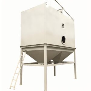
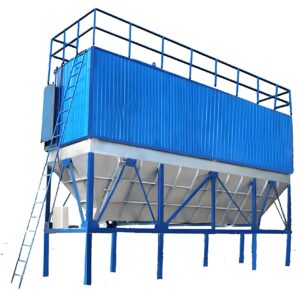
Industrial dust collection is a critical component of manufacturing facilities, woodworking shops, and processing plants. Among the various options available, cyclone dust collectors stand out for their efficiency and reliability in removing particulate matter from air streams. These conical devices use centrifugal force to separate dust particles from the airflow, making them particularly effective for medium to large-sized particles.
I recently toured a furniture manufacturing facility where the installation of a proper cyclone system transformed their operation. Before the upgrade, the shop floor was constantly covered in a fine layer of wood dust, creating both safety hazards and quality control issues. After implementing a well-designed cyclone dust collector installation, the air quality improved dramatically, and the maintenance team reported a 60% reduction in cleanup time.
Cyclone dust collectors offer several advantages over other filtration methods. They require minimal maintenance, have no moving parts in the separation chamber, and can handle heavy dust loads continuously. However, achieving these benefits depends entirely on proper installation. A correctly installed cyclone operates efficiently with lower energy costs, while poor installation can lead to reduced collection efficiency, excessive wear, and even system failure.
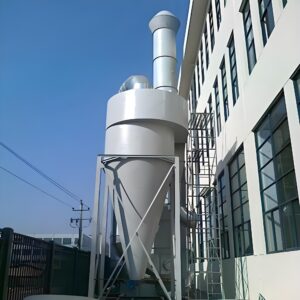
The fundamental principle behind PORVOO cyclone separators is straightforward but elegant – the incoming dust-laden air enters the cylindrical section tangentially, creating a vortex. The heavier particles are thrown outward against the walls and spiral downward into the collection chamber, while the cleaned air reverses direction and exits through the top.
As someone who’s personally supervised multiple industrial cyclone dust collector installations, I can attest that following a systematic approach is essential for success. This guide will walk through the seven critical steps for proper installation, highlighting important considerations at each stage.
Planning Your Cyclone Dust Collector Installation
Before ordering equipment or beginning any physical work, thorough planning is essential. I’ve witnessed projects face costly delays because fundamental questions weren’t addressed during the planning phase.
The first consideration is determining your dust collection needs. This involves calculating the volume of dust generated, the types of machines to be connected, and the required airflow. From my experience, it’s better to oversize slightly than to install an inadequate system that will struggle to keep up with demand.
Site evaluation is equally important. During a recent consultation at a metal fabrication facility, we discovered that the initially proposed installation location would have required expensive ductwork modifications. By relocating the industrial cyclone dust collector to a more central position, we reduced the total duct length by 40%, improving system efficiency while lowering installation costs.
Safety regulations must also be considered early in the planning process. Environmental engineer Dr. Sarah Chen emphasizes, “Local regulations often dictate minimum requirements for dust collection systems, particularly for combustible dusts. These requirements should be identified and incorporated into the installation plan from the beginning.”
Here’s a comprehensive breakdown of the tools and equipment you’ll need:
| Category | Essential Items | Optional but Recommended | Notes |
|---|---|---|---|
| Hand Tools | Wrenches, screwdrivers, pliers, measuring tape, level | Ratchet set, socket set | Metric and standard sizes may be needed depending on manufacturer |
| Power Tools | Drill with metal bits, impact driver | Angle grinder, reciprocating saw | Battery-powered tools provide mobility on larger installations |
| Safety Equipment | Hard hat, safety glasses, gloves, dust mask | Fall protection, hearing protection | Required PPE may vary based on facility requirements |
| Lifting Equipment | Forklift or crane (depending on unit size) | Chain hoist, straps | Weight capacity must exceed cyclone weight by at least 25% |
| Sealing Materials | Silicone sealant, gasket material, duct tape | Metal tape, mastic | High-temperature sealants may be required for certain applications |
| Testing Equipment | Anemometer, manometer | Particle counter, thermal camera | Essential for system verification and troubleshooting |
I’ve found that having the right equipment ready before beginning saves tremendous time compared to halting installation to source additional tools. For a recent pharmaceutical plant installation, we created a dedicated tool cart that moved with our team through each phase of the project.
Understanding system specifications is crucial for proper sizing and selection. Here’s a basic guide:
| System Size | Recommended CFM | Maximum Static Pressure | Typical Application | Installation Space Required |
|---|---|---|---|---|
| Small | 800-2,000 CFM | 4-6″ WC | Small woodshops, single machine collection | 8′ × 8′ area with 12′ ceiling height |
| Medium | 2,000-5,000 CFM | 6-8″ WC | Small manufacturing facilities, multiple machine collection | 10′ × 10′ area with 14-16′ ceiling height |
| Large | 5,000-15,000 CFM | 8-12″ WC | Large manufacturing, heavy dust production | 15′ × 15′ area with 18’+ ceiling height |
| Industrial | 15,000+ CFM | 12-20″+ WC | Heavy industrial applications, continuous operation | Custom requirements based on system specifications |
| *Note: Additional space needed for maintenance access and dust removal |
When planning the system layout, factor in future expansion possibilities. A manufacturing consultant I worked with suggests, “Design your initial ductwork with 20% additional capacity. The incremental cost during installation is minimal compared to retrofitting later.”
Step 1: Preparing the Installation Site
Site preparation is often underestimated but critically important for cyclone dust collector installation. I once consulted on a project where inadequate foundation preparation resulted in excessive vibration, reduced efficiency, and eventually required costly remediation.
Begin by verifying that the selected location meets all spatial requirements. The high-efficiency cyclone dust collector requires adequate vertical clearance for the main body plus additional space for ductwork connections. Horizontal clearance must allow for maintenance access and dust removal operations.
Foundation requirements depend on the system size and weight. For larger industrial units, a reinforced concrete pad is typically necessary. The foundation should extend at least 12 inches beyond the footprint of the unit in all directions and be level within ±1/8 inch across the entire surface. During a recent paper mill installation, we discovered that the existing concrete had deteriorated significantly. Taking the time to pour a new foundation added two days to our schedule but prevented potential alignment and vibration issues.
Environmental considerations are equally important. If your cyclone dust collection system will be installed outdoors, weather protection and drainage must be addressed. For one outdoor installation in a rainy climate, we integrated a sloped concrete pad with drainage channels to prevent water accumulation around the unit base.
Utility connections should be identified and prepared in advance:
- Electrical service: Confirm voltage, phase, and amperage requirements. Plan conduit pathways and disconnect location.
- Compressed air (if pneumatic discharge is used): Ensure adequate volume and pressure are available.
- Water connections (for wet systems): Verify supply and drainage capabilities.
- Network connectivity (for systems with remote monitoring): Plan cable routing or wireless access points.
Brandon Miller, a facility planning engineer, notes: “The most successful installations I’ve supervised include detailed utility planning. Mapping out exactly where each connection will be made before the equipment arrives prevents costly delays and impromptu solutions.”
For indoor installations, structural considerations become paramount. When installing a medium-sized cyclone in a warehouse with limited floor space, I worked with a structural engineer to design a mezzanine-mounted system. This required careful load calculations for the supporting structure and special vibration isolation to prevent noise transmission to the building frame.
A critical but often overlooked aspect of site preparation is the coordination with existing operations. In active facilities, installation work may need to be scheduled during non-production hours or phased to minimize disruption. During a recent installation at a continuously operating food processing plant, we created a detailed hour-by-hour schedule that allowed for system installation without forcing a complete production shutdown.
Step 2: Assembling the Cyclone Body
With the site prepared, it’s time to focus on assembling the cyclone body itself. This step requires attention to detail, as proper assembly directly impacts collection efficiency and system longevity.
The first task is to carefully unpack and organize all components. I recommend creating a staging area where parts can be laid out methodically. During a recent cyclone dust collector installation for a ceramics manufacturer, we used colored tape to mark the floor and arranged components by assembly sequence, significantly reducing our installation time.
Modern industrial cyclones typically arrive partially assembled, but some connection work will be necessary. Begin by identifying the main sections:
- The inlet section (with tangential entry port)
- The cylindrical barrel section
- The conical section
- The dust collection hopper
- The clean air outlet (vortex finder)
When assembling these components, follow the manufacturer’s torque specifications. I’ve seen installations where over-tightened connections distorted the cyclone body, creating air leaks and reducing efficiency. Conversely, under-tightened connections may work loose during operation.
Gaskets and sealing are critical aspects of assembly. Every connection must be airtight to maintain proper pressure and prevent dust escape. During an installation at a pharmaceutical facility, we used food-grade silicone sealant on all connections as an additional precaution against leaks, since even minor dust escape could compromise product quality.
Pay special attention to the vortex finder (the vertical tube that extends down from the top of the cyclone). Its position is critical for proper cyclone function. The bottom edge should extend below the tangential inlet but not so far that it disrupts the vortex formation. Most manufacturers provide specific positioning guidelines, but I’ve found that a distance of 1.5 times the inlet diameter below the inlet bottom edge is generally effective.
For larger industrial units, assembly may require lifting equipment. Safety protocols must be rigorously followed during this phase. When installing a 12-foot tall cyclone for a lumber mill, we used a combination of a forklift and chain hoists with spreader bars to properly position and align the sections without risking damage or workplace injuries.
Quality control checks should be performed throughout the assembly process:
- Verify all fasteners are correctly installed and torqued
- Inspect all seams for proper sealing
- Check that internal components (like vortex finder) are correctly positioned
- Confirm all access doors and inspection ports operate properly
- Verify the cyclone body is plumb (within 1° of vertical)
Dr. James Wong, an industrial ventilation expert, emphasizes: “The efficiency of a cyclone separator is highly dependent on its geometry being maintained during assembly. Even small deviations from design specifications can significantly impact performance.”
One often overlooked detail is the importance of removing any protective coverings from internal components. During a challenging installation at a grain processing facility, we discovered performance issues stemming from a plastic shipping cover that hadn’t been removed from an internal component. This small oversight caused significant efficiency problems that were difficult to diagnose after system completion.
Step 3: Installing the Collection System
With the cyclone body assembled, the next step involves proper positioning and securing of the unit. This critical phase establishes the foundation for your system’s long-term stability and performance.
Depending on your specific configuration, the cyclone may be floor-mounted, platform-mounted, or suspended from structural supports. Each mounting method has unique considerations. For floor-mounted installations, the unit must be precisely leveled and anchored to the foundation. I typically use adjustable mounting feet with vibration isolation pads to minimize noise transmission and compensate for minor foundation irregularities.
Alignment is absolutely critical during this phase. The cyclone must be installed plumb (vertically straight) to function properly. Even a slight tilt can significantly impact separation efficiency. On a recent installation at a wood products manufacturer, we discovered the concrete pad had a 3° slope. Rather than proceeding with a compromised installation, we fabricated custom mounting brackets with adjustable legs to achieve perfect vertical alignment.
For structural connections, I recommend using vibration isolation mounts between the cyclone and supporting structure. During a high-capacity industrial cyclone dust collector installation at a metal grinding facility, we incorporated spring isolators that reduced vibration transmission by 85%, according to our post-installation measurements.
The collection hopper warrants special attention. Its design and installation significantly impact how efficiently dust is collected and discharged. The hopper should have:
- A sufficient slope angle (typically 60° or greater) to prevent material buildup
- Appropriate volume capacity for your dust production
- Proper sealing at all access points
- Adequate clearance beneath for collection containers or conveying systems
Structural support requirements depend on the size and weight of your system. For a large installation at a cement processing facility, we had to reinforce existing support columns to handle the additional 3,200 pounds of the fully loaded cyclone. Working with a structural engineer is advisable for all but the smallest installations.
Anchor bolt selection and installation deserve careful attention. I generally recommend using anchor bolts with at least twice the load capacity calculated for the application. For a medium-sized cyclone installation, this typically means 5/8″ or 3/4″ anchor bolts with a minimum embedment of 4-6 inches into the concrete foundation.
Mike Fernandez, a facility maintenance director with 25 years of experience, shares: “I’ve seen too many dust collection systems that performed poorly simply because they weren’t properly secured. Over time, even minor movement can create air leaks or ductwork stress that degrades overall performance.”
Weather protection must be considered for outdoor installations. During a lumber mill project in the Pacific Northwest, we included a protective roof structure and weather-resistant coatings for all exposed components. The additional $4,500 investment extended the system’s lifespan by an estimated 7-10 years compared to unprotected units in similar environments.
Before proceeding to the next step, perform these essential quality checks:
- Verify the cyclone is perfectly plumb using a digital level
- Confirm all mounting hardware is properly tightened
- Check that vibration isolators are properly compressed
- Ensure adequate clearance exists for maintenance access
- Verify the collection container can be easily removed and replaced
Step 4: Connecting Ductwork
Ductwork is the circulatory system of your dust collection setup, and its proper installation dramatically impacts overall system performance. I’ve witnessed countless situations where excellent cyclone components were undermined by poor ductwork design and installation.
Begin with a comprehensive ductwork layout plan. This should include:
- Main trunk line sizing and routing
- Branch connection locations and sizes
- Transition pieces and reducing sections
- Blast gates and damper positions
- Support methods and spacing
Material selection for ductwork depends on your specific application. For woodworking operations, galvanized steel ducts of 18-22 gauge are typically sufficient. However, for abrasive materials or high-temperature applications, heavier gauge material or specialized options like stainless steel may be necessary. During an installation at a ceramic manufacturing facility, we used 16-gauge spiral-welded ductwork with abrasion-resistant coating to handle the highly abrasive clay dust.
The inlet connection is particularly important for cyclone efficiency. The tangential entry design creates the vortex action that separates particles from the airstream. This connection should maintain proper alignment without stress or distortion. For optimal performance, the inlet duct should approach the cyclone horizontally for at least three duct diameters before the connection.
Proper duct sealing is essential for system efficiency. Every leak reduces suction power and allows dust to escape. When connecting ductwork segments, I prefer to use self-tapping sheet metal screws at 4-inch intervals with mastic sealant applied to all joints. For a food processing plant installation where absolute dust containment was critical, we additionally used interior-applied silicone at each joint, achieving essentially zero leakage during pressure testing.
Support spacing for horizontal ductwork should generally follow these guidelines:
| Duct Diameter | Maximum Support Spacing | Recommended Support Type |
|---|---|---|
| Up to 8″ | 8 feet | Hanging strap or clevis hanger |
| 9″ to 16″ | 10 feet | Trapeze hanger or ring supports |
| 17″ to 24″ | 12 feet | Heavy-duty trapeze or angle iron supports |
| Over 24″ | 12 feet | Custom engineered supports |
| *Additional supports required at direction changes and branches |
Vertical duct runs require support at each floor or platform level and should not exceed 20 feet between supports. During a multi-story cyclone dust collector installation, we incorporated wall brackets at 15-foot intervals to provide additional stability.
Airflow balancing is a critical but often overlooked aspect of ductwork installation. To achieve proper balance:
- Install blast gates at each machine connection point
- Position dampers at strategic junction points in the system
- Ensure straight duct runs of at least 3-5 duct diameters before and after dampers
- Plan for future airflow testing access points
Alejandro Vega, an industrial ventilation specialist, notes: “The most common mistake I see is oversimplifying the ductwork design. A properly engineered system accounts for static pressure losses at every turn, transition, and branch connection.”
Branch connections deserve special attention. The ideal connection angle is 30° or less from the main trunk line, with a smooth transition piece rather than a sharp junction. At a recent installation for a cabinet manufacturer, we replaced several 90° branch connections with 30° entries, increasing airflow by approximately 15% throughout the system.
For turns and direction changes, use long-radius elbows whenever possible. The centerline radius should be at least 1.5 times the duct diameter for optimal airflow. When space constraints make this impossible, install turning vanes in sharp elbows to reduce turbulence and pressure drop.
Before finalizing ductwork connections, verify that:
- All seams are properly sealed
- Support spacing meets or exceeds recommendations
- Flex connections are used at the blower to minimize vibration transfer
- Adequate clearance exists for system maintenance
- Blast gates and dampers operate smoothly
- All components are properly grounded to prevent static buildup
Step 5: Installing the Discharge System
The discharge system might seem straightforward, but its proper installation is critical for maintaining cyclone efficiency and providing convenient dust disposal. I’ve consulted on numerous troubleshooting projects where discharge system issues were the hidden culprit behind poor collection performance.
The primary components of the discharge system typically include:
- Airlock or rotary valve (for continuous operation)
- Collection container or drum
- Transition connections
- Dust handling mechanisms
The airlock valve serves a critical function in the high-efficiency industrial cyclone dust collector, maintaining system pressure while allowing dust to exit. When installing the airlock, precise alignment is essential. Even slight misalignment can cause premature bearing wear, air leakage, or jamming. I recommend using a laser level to achieve perfect alignment between the cyclone outlet and the airlock inlet.
For appropriate airlock selection, consider these factors:
- Material characteristics (abrasiveness, density, moisture content)
- Required throughput capacity
- Operating environment (temperature, humidity, corrosive elements)
- Drive type (direct drive, chain drive, belt drive)
- Rotation speed requirements
During installation at a plastic pellet manufacturing facility, we discovered that the standard airlock wasn’t suitable for their material. We replaced it with a high-temperature model with hardened steel rotor tips, which extended maintenance intervals from monthly to quarterly.
Collection containers must be properly sized based on dust volume and emptying frequency. For operations with high dust production, consider automated discharge systems like screw conveyors or pneumatic transport. At a furniture manufacturing operation, we replaced their manual drum system with a custom screw conveyor that transported sawdust directly to their biomass boiler, eliminating the labor-intensive drum handling process entirely.
Sealing between components is particularly important in the discharge system. Any air leakage here creates a path of least resistance that reduces system efficiency. For critical applications, I recommend using compression gaskets with adjustable clamps rather than standard flat gaskets. This approach has proven effective even in high-vibration environments.
Dust disposal considerations should factor into your installation planning. In a woodworking facility where I recently consulted, we designed a discharge system with quick-disconnect fittings that allowed forklift operators to swap full containers with empties in under 30 seconds, minimizing system downtime.
Safety features are essential in discharge system design. These should include:
- Emergency stop capability
- Proper lockout/tagout provisions
- Guards for moving components
- Dust containment during container changes
- Anti-bridging devices for problematic materials
Level indicators or alert systems can be valuable additions to your discharge system. During an agricultural processing plant installation, we incorporated ultrasonic level sensors that alerted operators when the collection containers reached 80% capacity, preventing overflow situations that had previously caused system shutdowns.
Environmental engineer Melissa Chang recommends: “For materials with environmental disposal restrictions, incorporate containment features in your discharge design. This might include sealed containers, dust suppression systems, or specialized handling equipment.”
For facilities dealing with combustible dust, additional safeguards may be necessary in the discharge system. These might include explosion venting, oxygen monitoring, or spark detection systems. The National Fire Protection Association (NFPA) provides specific guidelines that should be carefully followed.
Before finalizing the discharge system installation, verify:
- All components are properly aligned and secured
- Seals and gaskets are correctly installed
- Access points allow for easy maintenance
- Safety features function as intended
- The system can handle peak dust loads without backup or overflow
Step 6: Electrical Connections and Control System
The electrical and control systems bring your cyclone dust collector to life, transforming it from a passive device into an intelligent, responsive system. I’ve found that thoughtful control system installation can dramatically improve ease of operation, energy efficiency, and overall system performance.
Begin by reviewing the electrical requirements specified by the manufacturer. These typically include:
- Voltage and phase requirements
- Full load amperage
- Control circuit specifications
- Motor starter sizing
- Recommended wire gauge
All electrical work should comply with local codes and the National Electrical Code (NEC). When installing a system at a metal fabrication facility, we discovered their existing electrical service wasn’t adequate for the new cyclone system. Working with a licensed electrician, we upgraded their service panel and installed dedicated circuits before proceeding.
The control panel location deserves careful consideration. It should be:
- Easily accessible for operators
- Protected from dust and moisture
- Visible from the main equipment area
- Away from excessive heat or vibration
- Positioned to allow observation of the system during startup
Modern control systems offer various automation options that can significantly enhance operation. During a recent installation, we incorporated a programmable logic controller (PLC) that automatically adjusted fan speed based on which machines were operating, resulting in a 23% energy savings compared to their previous fixed-speed system.
Safety interlocks are an essential component of your control system. These might include:
- Emergency stop buttons at strategic locations
- Interlock switches on access doors
- Motor overload protection
- Airflow monitoring with automatic shutdown for blockages
- Bearing temperature monitoring on larger systems
For facilities with multiple dust-producing machines, consider implementing automated blast gate controls. This approach ensures optimal airflow to active machines while reducing overall system demand. At a cabinet shop installation, we used motorized blast gates with proximity sensors that detected when machines were operating, automatically opening gates only when needed.
“The most effective dust collection systems I’ve encountered use variable frequency drives (VFDs) on the main fan motor,” notes electrical engineer Tom Wilson. “This allows the system to maintain optimal duct velocity regardless of how many collection points are active, saving energy while extending filter life.”
For systems requiring special monitoring, consider incorporating these advanced features:
- Differential pressure monitoring across the cyclone
- Rotary valve rotation monitoring
- Collection container level sensors
- Remote monitoring capabilities via network connection
- Data logging for performance analysis
When installing the main fan motor, proper alignment is critical to prevent premature bearing failure and excessive vibration. I always recommend using a laser alignment tool to achieve precise coupling alignment, rather than relying on visual inspection.
Overload protection should be carefully sized according to the motor specifications. For a woodworking facility with frequent startups throughout the day, we selected oversized thermal overload relays to handle the additional heat generated by multiple daily startup cycles.
Operational controls should be intuitive and clearly labeled. When designing the control interface for a training facility with multiple operators, we used color-coded controls and graphic displays that reduced operator errors by over 80% compared to their previous text-based system.
Electrical connections to the discharge system deserve special attention, particularly for powering rotary airlocks or screw conveyors. These components often operate in dusty environments where proper sealing and appropriate conduit installations are essential for safety and reliability.
Before energizing the system, perform a complete inspection:
- Verify all connections are tight and properly terminated
- Confirm proper grounding throughout the system
- Check motor rotation direction before connecting to mechanical loads
- Test all safety circuits and interlocks
- Verify control functions operate as designed
- Ensure all conduit connections are properly sealed
Step 7: Testing and Commissioning
The final step in your cyclone dust collector installation is comprehensive testing and commissioning. This phase transforms your carefully installed components into a properly functioning system. I’ve found that thorough testing not only confirms proper operation but often identifies minor adjustments that can significantly improve long-term performance.
Begin with a methodical pre-startup inspection:
- Verify all mechanical connections are tight
- Confirm all access doors and panels are secured
- Check that all safety guards are in place
- Ensure all electrical connections are complete and properly terminated
- Verify blast gates are in their correct positions
- Confirm the collection container is properly installed
- Check that no tools or materials have been left inside the system
The initial startup should follow a specific sequence:
- Power up control systems without starting motors
- Verify all indicators and gauges function correctly
- Start the discharge system (airlock or rotary valve) first
- Start the main fan motor next
- Listen for unusual noises or vibrations
- Monitor motor amp draw during startup
- Observe system pressure readings
During my recent commissioning of a specialized cyclone dust collector installation for a pharmaceutical manufacturer, we discovered excessive vibration during initial startup. Careful inspection revealed that shipping braces had not been removed from the fan assembly. This simple oversight could have caused significant damage if not identified during commissioning.
Airflow testing is essential for verifying system performance. Using an anemometer, measure air velocity at:
- The main inlet duct
- Branch connections
- Pickup points at machines
- The clean air outlet
Compare these readings to the design specifications. In my experience, most systems require some adjustment to achieve optimal performance. During a woodworking shop installation, we discovered airflow at distant collection points was 30% below specification. By adjusting dampers and modifying several duct transitions, we achieved balanced airflow throughout the system.
Static pressure measurements provide valuable insight into system operation. Test at these key points:
- Across the cyclone (inlet to outlet)
- At the main fan inlet
- At the furthest collection point
- At any suspicious restrictions
When commissioning a large system for a furniture manufacturer, our pressure testing revealed an unexpected restriction. Further investigation discovered a worker’s hardhat had been accidentally left inside a duct section during installation. This humorous but instructive incident demonstrates the importance of thorough testing.
System balancing involves adjusting dampers and blast gates to achieve proper airflow distribution. Start with all gates fully open, then systematically adjust each one while monitoring the effect on the overall system. Document the final positions for future reference.
| Testing Parameter | Acceptable Range | Warning Signs | Corrective Actions |
|---|---|---|---|
| Velocity in main duct | 3,500-4,500 FPM | <3,000 or >5,000 FPM | Adjust fan speed, modify duct size, check for restrictions |
| Static pressure across cyclone | Manufacturer spec ±10% | Excessive pressure drop | Check for internal blockages, verify inlet alignment |
| Motor amp draw | ≤ Full load amps | Near or exceeding FLA | Check for system restrictions, verify proper motor sizing |
| Vibration levels | <0.15 in/sec velocity | >0.25 in/sec | Check alignment, balance, and mounting connections |
| Sound levels | <85 dBA at operator position | >90 dBA | Verify proper installation of vibration isolation, check for air leaks |
| *Note: Specific parameters may vary based on manufacturer recommendations and system design |
Performance verification should include testing with actual production material. During a metal grinding shop installation, the system performed well with test material but struggled with the finer particles produced during actual production. We modified the inlet configuration to create a stronger vortex action, improving fine particle separation by approximately 35%.
Joel Martinez, a dust collection specialist with 18 years of experience, advises: “Always test the system under worst-case conditions. If multiple machines will sometimes operate simultaneously, test with that configuration to ensure adequate performance.”
Documentation is a critical component of commissioning. Create a comprehensive system file that includes:
- As-built drawings showing actual installation details
- Performance test results compared to design specifications
- Equipment serial numbers and warranty information
- Maintenance requirements and schedules
- Troubleshooting guidelines for common issues
- Vendor contact information
Training operators and maintenance personnel is the final commissioning step. For a recent installation at a training facility, we created a simplified one-page operation guide with color-coded controls that reduced training time from two days to four hours while improving operational consistency.
Maintenance Best Practices for Cyclone Dust Collectors
Proper maintenance ensures your cyclone dust collector delivers consistent performance and achieves its expected service life. Having supervised maintenance programs for numerous industrial installations, I’ve found that well-maintained systems often exceed their design lifespans by 30% or more.
Establish a regular inspection schedule based on your operating conditions. For continuous operations in high-dust environments, weekly visual inspections are advisable. During a consulting project for a busy furniture manufacturer, we implemented a daily 5-minute inspection routine that caught minor issues before they developed into costly problems.
The cyclone body itself requires relatively little maintenance, but regular inspection for these issues is important:
- Wear patterns on the inner walls, particularly near the inlet
- Material buildup that might disrupt the airflow pattern
- Corrosion or damage to the cyclone body
- Proper function of the vortex finder
- Intact seals at all
Frequently Asked Questions of cyclone dust collector installation
Q: What is involved in a proper cyclone dust collector installation?
A: Proper cyclone dust collector installation involves several key steps, including selecting an appropriate location, assembling the components, securing the hopper and cyclone units, and ensuring all safety precautions are taken. It’s crucial to use proper lifting equipment and distribute the load evenly to avoid accidents. Also, ensure the site is clear of obstructions like utility lines.
Q: How do I ensure safety during cyclone dust collector installation?
A: Safety during installation is paramount. Use lifting slings attached to multiple points to distribute the weight evenly, ensuring no obstructions such as utility lines or roof overhangs are nearby. Always follow manufacturer guidelines and use appropriate lifting equipment to prevent personal injury or property damage.
Q: What are the benefits of using a cyclone dust collector in industrial settings?
A: Cyclone dust collectors offer several benefits, including efficient dust removal, reduced maintenance compared to other systems, and improved air quality by capturing large dust particles effectively. They are also cost-effective and can handle heavy-duty industrial applications.
Q: How do I maintain and clean my cyclone dust collector after installation?
A: Maintenance involves regular cleaning of the dust collection drum and ensuring all moving parts are functioning properly. Check for blockages and clean the inlet and outlet transitions as needed. Regular inspection helps extend the lifespan of the collector.
Q: Can I upgrade my existing dust collector to a cyclone system?
A: Yes, upgrading to a cyclone dust collector is feasible. This can be done by integrating a cyclone unit into your existing setup or by adding a canister to enhance dust collection efficiency. Such upgrades can improve the overall performance of your dust collection system.
Q: Are there specific considerations for handling combustible materials with cyclone dust collectors?
A: When handling combustible materials, it’s crucial to take special care. Ensure that your cyclone dust collector installation is designed to manage such risks. Use materials and components that are safe for combustible environments and follow all safety guidelines to minimize the risk of fire or explosion.
External Resources
- Parker Hannifin – Cyclone Dust Collector User Guide – Provides detailed instructions and safety precautions for installing and operating Parker Hannifin’s high-efficiency cyclone dust collectors.
- Donaldson Company – Cyclone Dust Collector IOM – Offers comprehensive installation and operation instructions for various sizes of Donaldson’s cyclone dust collectors.
- Woodcraft – Cyclone Dust Collection System Installation – Provides tips and insights into setting up an effective cyclone dust collection system for woodworking applications.
- Oneida Air Systems – Ductwork Installation Guide – Although not exclusively focused on cyclone dust collectors, this guide provides essential information on ductwork installation, crucial for effective dust collection system performance.
- Mullet Tools – Fitting Your Mullet High-Speed Cyclone Dust Collector – Offers installation guidance specifically for adapting the Mullet cyclone dust collector to shop vacuums.
- YouTube – Setting Up a Cyclone Dust Collector Upgrade – A practical video tutorial on upgrading single-stage dust collectors to two-stage systems using cyclone add-ons.
