Understanding Industrial Cyclone Dust Collectors
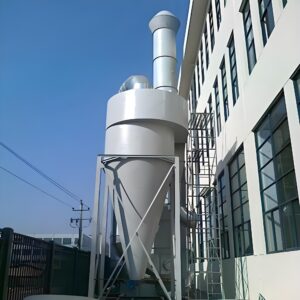
I’ve spent over a decade working with industrial air quality systems, and one thing consistently surprises facility managers: the seemingly simple cyclone dust collector is actually a marvel of physics and engineering. Rather than relying on filters or bags, cyclones use centrifugal force to separate particles from an air stream. When air enters the cylindrical upper section tangentially, it forms a spinning vortex. Heavier particles are flung outward against the walls and spiral downward, while clean air moves upward through the center and exits through the top outlet.
What makes cyclones particularly fascinating is how their performance hinges on precision design. The body consists of a cylindrical upper section (barrel) that transitions into a conical lower portion. The inlet directs contaminated air tangentially into the barrel, while the vortex finder (outlet tube) extends down from the top to prevent short-circuiting of the air flow. At the bottom, a dust collection hopper or bin collects the separated particles.
PORVOO’s cyclone dust collectors feature several key innovations that address common performance issues. Their designs incorporate optimized inlet geometries and carefully calculated dimensional ratios that maximize collection efficiency while minimizing pressure drop.
Cyclones generally fall into three main categories based on their collection efficiency:
| Cyclone Type | Collection Efficiency | Typical Applications | Pressure Drop |
|---|---|---|---|
| High-efficiency | 90-95% for particles >5μm | Fine dust, valuable material recovery | Higher (6-8″ w.g.) |
| Medium-efficiency | 85-90% for particles >10μm | General industrial applications | Moderate (4-6″ w.g.) |
| Low-efficiency | 75-85% for particles >20μm | Pre-filtration, large particle separation | Lower (2-4″ w.g.) |
What’s particularly interesting is how these different designs achieve their specific performance characteristics through subtle variations in proportions and dimensions. For instance, high-efficiency units typically feature longer cone sections and smaller diameter outlets, creating higher velocities and stronger centrifugal forces.
In woodworking shops, I’ve observed cyclones functioning as both standalone collectors and pre-separators before baghouses. Metal fabrication facilities often employ industrial cyclone dust collectors for capturing heavier grinding and blasting particles. Food processing plants utilize them for product recovery as much as for air cleaning.
The beauty of cyclones lies in their simplicity—no moving parts, no replacement filters, and minimal maintenance requirements when properly sized. And that last point is crucial, as we’ll explore next.
Why Proper Sizing is Critical
A conversation I had with a manufacturing plant manager last year really drove home the importance of cyclone sizing. “We installed what we thought was a top-of-the-line system,” he told me, “but our collection efficiency was terrible, and our energy bills went through the roof.” The problem? Their cyclone was significantly oversized for their application.
Proper cyclone dust collector sizing affects virtually every aspect of system performance. Let me break this down:
First, collection efficiency directly correlates with sizing parameters. An undersized cyclone simply won’t create sufficient centrifugal force to separate smaller particles. I’ve seen systems where efficiency dropped from an expected 90% to below 60% simply because the cyclone diameter was too large for the actual airflow. Conversely, an oversized unit with too much airflow can create turbulence that re-entrains particles back into the airstream.
Energy consumption represents another critical consideration. Cyclones inherently create pressure drop as air moves through them. This pressure drop must be overcome by fans, which consume energy. A properly sized cyclone strikes the optimal balance between collection efficiency and pressure drop. From my experience auditing industrial systems, improper sizing typically increases energy consumption by 15-30%—costs that accumulate rapidly over the system’s lifetime.
Maintenance requirements escalate dramatically with improper sizing. Undersized systems frequently clog, requiring frequent downtime for cleaning. I’ve witnessed maintenance teams having to clear cone sections weekly instead of monthly due to poor sizing decisions. Meanwhile, oversized systems often experience abrasion wear patterns that differ from design expectations, leading to premature component failure.
Perhaps most importantly in today’s regulatory environment, environmental compliance depends on achieving specified collection efficiencies. When I worked with a furniture manufacturer facing EPA scrutiny, their improperly sized cyclones were allowing fine wood dust to escape in quantities that exceeded permissible limits. The retrofit costs far exceeded what proper initial sizing would have required.
Dr. Alexander Hoffmann, whose research I’ve followed for years, emphasizes that “the ratio between operating flowrate and design flowrate should ideally remain between 0.8 and.1.2 to maintain predicted separation efficiency.” Beyond this range, performance degrades exponentially.
This brings us to a fundamental understanding: cyclone dust collector sizing isn’t just a technical specification—it’s the foundation upon which the entire system’s performance, efficiency, and economic viability rest.
Key Parameters for Cyclone Sizing
When I first started designing dust collection systems, I approached cyclone sizing as a straightforward calculation based primarily on airflow. Years of troubleshooting poorly performing systems taught me that effective cyclone dust collector sizing involves a complex interplay of multiple parameters.
Airflow requirements form the foundation of any sizing exercise. You’ll need to determine the total cubic feet per minute (CFM) required to capture dust at each source point. This involves calculating:
- Capture velocity at the source (typically 100-200 ft/min for fine dusts)
- Transport velocity in ductwork (usually 3,500-4,500 ft/min for wood dust)
- Total system volume requirements
During a recent manufacturing facility assessment, we discovered their system was designed for 10,000 CFM, but actual production requirements were closer to 14,000 CFM. This discrepancy meant their cyclone was processing approximately 40% more air than designed, reducing collection efficiency dramatically.
Particle characteristics significantly influence cyclone performance and sizing decisions. Consider these critical factors:
| Particle Property | Impact on Sizing | Measurement Method | Typical Range |
|---|---|---|---|
| Size distribution | Determines minimum cyclone diameter for target efficiency | Particle size analysis | 1-100+ microns |
| Density | Affects separation forces | Material density testing | 0.5-8+ g/cm³ |
| Shape | Influences drag and separation behavior | Microscopic analysis | Varies widely |
| Moisture content | Affects particle agglomeration and wall adhesion | Moisture analysis | 0-30% |
I once worked on a metal fabrication facility where the particle size distribution analysis revealed an unexpectedly high percentage of sub-5 micron particles. This insight led us to specify a high-efficiency cyclone design with modified proportions rather than a standard unit.
Pressure drop considerations cannot be overlooked. The pressure drop across a cyclone generally increases with the square of the airflow velocity. Finding the sweet spot is critical—too little pressure drop means insufficient centrifugal force for separation; too much means excessive energy consumption. Most industrial cyclones operate with pressure drops between 2-8 inches water gauge (in. w.g.).
The American Conference of Governmental Industrial Hygienists (ACGIH) guidelines suggest that well-designed cyclones should achieve their rated efficiency at pressure drops that don’t exceed 4-6 in. w.g. for standard applications.
Space constraints often dictate practical limitations. While a larger diameter cyclone might offer lower pressure drop, installation realities sometimes necessitate compact designs. In a brewery I consulted for, ceiling height limitations forced us to consider a multi-cyclone arrangement rather than a single larger unit.
ASHRAE’s technical committee on industrial air cleaning notes that the critical dimensional ratios in cyclone design include:
- Inlet height to cyclone diameter (typically 0.5-0.7)
- Outlet diameter to cyclone diameter (typically 0.4-0.6)
- Overall height to cyclone diameter (typically 3-5)
Adjusting these ratios allows designers to optimize performance for specific conditions, as I’ve seen with high-efficiency cyclone collectors that modify standard proportions to enhance fine particle capture.
Temperature and humidity conditions must also factor into your calculations. Hot gases have lower density, affecting particle separation. Moisture can cause material buildup on cyclone walls, potentially altering the interior geometry over time. I’ve observed this particularly in food processing applications, where periodic cleaning becomes essential to maintain design performance.
Step-by-Step Sizing Methodology
Over my years in the field, I’ve refined a systematic approach to cyclone sizing that balances theoretical calculations with practical considerations. Let me walk you through this methodology step by step.
Begin with a comprehensive dust source assessment. This involves identifying all dust generation points and characterizing the material properties. Last year, I worked with a woodworking facility that initially provided “standard wood dust” as their only material description. After proper assessment, we discovered their operation produced everything from fine sanding dust to heavy shavings—each requiring different collection parameters.
For accurate airflow requirements, measure or calculate the necessary capture velocity at each workstation. Then determine duct transport velocities based on the heaviest particles present. Add these values to establish your baseline system CFM requirements. Document these clearly, as they’ll form the foundation of your sizing calculations.
Next, characterize your dust properties thoroughly. A particle size distribution analysis is invaluable here—it shows the percentage of particles in each size range. When working with a pharmaceutical manufacturer, we discovered that though their process generally produced coarse powders, one specific operation generated significant quantities of sub-5-micron particles. This insight fundamentally changed our cyclone selection.
With this foundational data established, you can proceed to cyclone selection and sizing using one of several approaches:
Theoretical equations: Mathematical models like the Lapple Model or the Leith and Licht approach can predict cyclone performance. These equations incorporate parameters such as gas viscosity, particle density, cyclone dimensions, and volumetric flow rate.
Manufacturer data: Companies like PORVOO provide performance curves showing efficiency versus particle size for different models.
Computational tools: Software packages that model cyclone performance based on your specific inputs.
For most industrial applications, I recommend a hybrid approach. Start with theoretical calculations to establish baseline parameters, then refine using manufacturer data. As an example, consider this simplified sizing sequence for a woodworking application:
- Establish required airflow: 5,000 CFM
- Determine primary particle size range: 10-100 microns
- Calculate ideal cyclone diameter using the equation:
D = √(Q/3.14 × Vin)
Where D is diameter in feet, Q is airflow in CFM, and Vin is inlet velocity (typically 3,000-4,000 ft/min) - Check resulting pressure drop against system capabilities
- Validate separation efficiency using manufacturer performance curves
When I applied this approach for a furniture manufacturer, our calculations indicated a 48-inch diameter cyclone would be optimal. However, the manufacturer’s performance data showed that a 42-inch high-efficiency cyclone model with modified inlet dimensions could achieve the required efficiency with a more favorable pressure drop profile.
For complex applications, I recommend conducting a sensitivity analysis. This involves calculating performance across a range of potential operating conditions—not just the design point. During a project for a variable-output production facility, this analysis revealed that a slightly larger cyclone would maintain acceptable efficiency across their entire operating range.
After sizing, validation becomes critical. For new installations, consider these verification methods:
- CFD (Computational Fluid Dynamics) modeling for complex systems
- Pilot testing for unique dust characteristics
- Performance guarantee testing after installation
I’ve found emission testing particularly valuable for regulatory compliance verification. During commissioning of a food processing cyclone system, we conducted fractional efficiency tests across different particle sizes, confirming our sizing calculations achieved the required 94% overall efficiency.
One often overlooked aspect is system expansion potential. I always ask clients about future production increases or additional collection points. Sizing with 10-20% extra capacity can often be justified when weighed against the costs of future upgrades.
Common Sizing Mistakes and How to Avoid Them
Throughout my career inspecting industrial ventilation systems, I’ve encountered the same sizing mistakes repeatedly. Let me share the most common ones I’ve observed so you can avoid them.
Overlooking actual particle characteristics might be the single most prevalent error. Too often, I see facilities select cyclones based on generic dust descriptions rather than actual analysis. A metal fabrication shop I visited had installed a standard efficiency cyclone for what they described as “typical metal dust.” When we analyzed their actual dust, we found a significant fraction of ultrafine particles from precision grinding operations—particles their cyclone simply wasn’t designed to capture. Always base your sizing on measured particle characteristics, not assumptions.
Failure to account for actual operating airflow represents another critical mistake. Systems rarely operate exactly at their design point. I recall a plastics processing facility that sized their cyclone for 7,500 CFM, but their actual system operated between 6,000-9,000 CFM depending on which machines were running. At the lower flow rates, gas velocity was insufficient for proper separation, while higher flows created excessive pressure drop and turbulence. Consider variable frequency drives (VFDs) on fan systems where substantial flow variations are expected.
System effect factors are frequently neglected in calculations. These are the pressure losses that occur due to non-ideal inlet and outlet conditions. During a recent system assessment, I discovered a cyclone performing well below expectations despite correct diameter sizing. The culprit? A 90-degree elbow positioned just three duct diameters before the cyclone inlet, creating turbulent, asymmetrical flow. Following ACGIH guidelines for straight duct runs before and after cyclones (typically 5-10 duct diameters) helps avoid this issue.
Improper application of safety factors leads to oversizing more often than undersizing. While some margin is prudent, excessive oversizing creates its own problems. I’ve witnessed facilities applying 50% safety factors on airflow calculations, resulting in cyclones operating well below optimal velocity ranges. A more reasonable approach involves applying specific margins to individual parameters rather than blanket oversizing.
Temperature effects receive too little attention in many calculations. A cement plant I consulted for had sized their cyclone based on standard conditions, but their actual process generated dust at temperatures exceeding 180°F. The reduced gas density at elevated temperatures significantly altered the cyclone’s separation characteristics. Always adjust your calculations for actual operating temperatures, particularly in high-temperature applications.
Ignoring cyclone orientation and mounting position can compromise performance. While reviewing a failing system at a grain processing facility, I discovered their cyclone had been mounted horizontally to accommodate space constraints—completely altering the separation dynamics. Though some specialized designs can accommodate non-vertical orientations, standard cyclone dust collectors rely on gravity for proper particle discharge and must be mounted vertically.
Neglecting proper dust discharge systems undermines even perfect sizing calculations. A perfectly sized cyclone will fail if particles can’t properly exit the collection point. I’ve seen systems where collected material backed up into the cyclone cone because the airlock valve was undersized for the volume of material collected. Size your discharge system for peak dust loading conditions, not just average volumes.
Failure to consider future needs leads to premature obsolescence. During infrastructure upgrades at a woodworking facility, I encountered a relatively new cyclone that required replacement because production had increased 30% within two years of installation. When sizing, discuss future production plans with management and consider whether modest upsizing might provide valuable flexibility.
Case Studies: Successful Cyclone Sizing in Different Industries
The principles of cyclone sizing come to life through real-world applications. Let me share some illuminating cases I’ve encountered that demonstrate how proper sizing addresses industry-specific challenges.
In a large furniture manufacturing facility in North Carolina, the production floor generated over 2 tons of wood waste daily from various operations including sawing, planing, and sanding. Their existing cyclone system struggled with efficiency, allowing fine dust to reach the baghouse filters, which required frequent replacement. Upon investigation, I discovered their cyclone was sized based solely on total airflow (25,000 CFM) without considering the particle size distribution.
We conducted a comprehensive dust analysis that revealed approximately 30% of their dust consisted of particles smaller than 10 microns—primarily from sanding operations. Based on this data, we specified a PORVOO high-efficiency cyclonic dust collector with modified dimensional ratios: a smaller outlet diameter relative to the cyclone body and an extended conical section. These modifications increased the centrifugal forces acting on smaller particles.
The results were remarkable: overall collection efficiency increased from 82% to 94%, the load on the secondary filters decreased by approximately 65%, and the pressure drop across the system actually decreased due to less restricted secondary filters. The payback period on the investment was just 14 months through reduced maintenance costs and energy savings.
| Performance Metric | Before Resizing | After Proper Sizing | Improvement |
|---|---|---|---|
| Collection Efficiency | 82% | 94% | 12% |
| Secondary Filter Load | 100% (baseline) | 35% | 65% reduction |
| Filter Replacement Frequency | Every 3 months | Every 11 months | 73% reduction |
| System Pressure Drop | 8.4″ w.g. | 7.1″ w.g. | 15% reduction |
| Annual Maintenance Costs | $42,500 | $14,800 | 65% savings |
A different challenge emerged at a metalworking facility that produced various grades of steel dust from grinding, blasting, and cutting operations. Their existing cyclone system was undersized for their airflow requirements, resulting in excessive emissions and recurring EPA compliance issues.
The facility had expanded operations over the years without corresponding dust collection upgrades. Their existing cyclone processed approximately 12,000 CFM despite being designed for only 8,000 CFM. The excessive velocity created turbulence within the cyclone, reducing separation efficiency and causing premature wear along the cyclone walls.
Working with their team, we conducted detailed airflow studies at each workstation and particle analysis of the various dusts. The metal particles were relatively dense (specific gravity around 7.8) but varied dramatically in size. Based on these findings, we implemented a multi-cyclone approach rather than a single larger unit.
The new system utilized four parallel cyclones, each handling 4,000 CFM and optimized for a specific particle size range. This modular approach allowed the facility to operate different production areas independently, saving energy during partial production runs. Collection efficiency improved from approximately 70% to over 95%, bringing them well within compliance requirements. An unexpected benefit was the improved material recovery—the cleaner separated metal dust now had sufficient value for recycling, creating a new revenue stream.
In a food processing application—a large rice milling facility—the challenges were quite different. The dust included particles with varying densities, from light rice husks to heavier grain fragments. Additionally, the system needed to handle significant seasonal variations in production volume.
The existing cyclone was actually oversized for the typical operation, resulting in insufficient separation velocity during normal production. However, during peak season, the system operated near capacity. This variable operation made sizing particularly challenging.
Our solution involved a correctly sized primary cyclone with an inlet damper system connected to the facility’s production management software. The damper automatically adjusted based on the active processing lines, maintaining optimal velocity within the cyclone regardless of total system airflow. We also incorporated a variable frequency drive on the fan system to reduce energy consumption during lower airflow periods.
The results demonstrated the importance of systemic thinking in cyclone sizing. Energy consumption decreased by 27% annually, while collection efficiency remained consistently above 90% regardless of production rates. Perhaps most importantly, the seasonally variable cleaning and maintenance requirements became predictable and could be scheduled appropriately.
Advanced Sizing Considerations
As systems grow more complex and regulatory requirements more stringent, advanced cyclone sizing considerations become increasingly important. Throughout my engineering career, I’ve found that these sophisticated approaches often make the difference between adequate and exceptional performance.
Multi-cyclone systems present unique sizing challenges and opportunities. Rather than installing a single large cyclone, these systems distribute airflow across multiple smaller units operating in parallel. During a project for a large grain processing facility, we found that four 36-inch cyclones actually outperformed a single 72-inch unit despite similar theoretical capacities. The smaller cyclones generated stronger centrifugal forces while maintaining manageable pressure drops.
When sizing multi-cyclone arrangements, consider:
- Equal airflow distribution across units (within ±10%)
- Proper header design to minimize turbulence
- Independent discharge systems for each cyclone
- Structural support requirements for the assembled array
I’ve found that computational fluid dynamics (CFD) modeling becomes particularly valuable when sizing complex systems. A pharmaceutical manufacturer I worked with required extremely high collection efficiency for valuable product recovery. Traditional sizing calculations suggested a standard high-efficiency design, but CFD modeling revealed problematic flow patterns at their specific operating conditions. We modified the vortex finder length and cone angle based on these simulations, achieving a 3% efficiency improvement—significant when processing high-value materials.
Temperature fluctuations require special sizing considerations. In a ceramic manufacturing facility, process temperatures varied from ambient to over 300°F depending on which kilns were operating. This variability significantly affected gas density and cyclone performance. Our solution incorporated temperature-responsive controls that adjusted fan speed to maintain optimal cyclone inlet velocity despite density changes. Consider temperature effects on:
- Gas density and viscosity
- Material characteristics (some dusts become sticky at elevated temperatures)
- Thermal expansion of cyclone components
- Potential condensation issues as gases cool
High-efficiency cyclone designs often incorporate modifications to standard proportional relationships. When specifying a system for a woodworking facility with stringent emission requirements, we utilized a cyclone with an extended cylindrical section and reduced outlet diameter. These modifications increased residence time and centrifugal forces, improving fine particle capture. However, such design adjustments also increased pressure drop, requiring careful fan selection.
| Design Feature | Standard Cyclone | High-Efficiency Modification | Performance Impact |
|---|---|---|---|
| Inlet height/diameter ratio | 0.5-0.7 | 0.4-0.5 | Increased inlet velocity |
| Outlet diameter/body diameter | 0.5-0.6 | 0.3-0.4 | Stronger vortex formation |
| Cone length/body diameter | 1.5-2.5 | 2.5-4.0 | Extended separation zone |
| Vortex finder length | 0.5-0.8× diameter | 0.8-1.2× diameter | Prevents short-circuiting |
Integration with secondary filtration systems requires thoughtful sizing decisions. I’ve designed numerous systems where cyclones serve as pre-separators for baghouses or cartridge filters. The proper cyclone sizing in these applications significantly extends secondary filter life. During a system upgrade at a plastic recycling facility, properly sizing the pre-separator cyclone reduced filter replacement frequency from monthly to quarterly, despite a 15% production increase.
Another advanced consideration involves sizing for abrasion resistance. In a mining operation processing highly abrasive minerals, we deliberately oversized the cyclone diameter by approximately 20% compared to theoretical calculations. This reduced gas velocity along the walls, extending the cyclone’s service life from approximately 8 months to over 2 years before requiring replacement of wear components.
Future-proofing your cyclone system should influence current sizing decisions. During consultations, I always recommend discussing anticipated production changes over the next 5-10 years. Installing cyclone dust collectors with moderate excess capacity can accommodate future growth without major retrofits. However, this approach requires careful balance—too much oversizing impacts current performance, while insufficient margin limits expansion potential.
For facilities with variable production, consider modular designs where possible. A manufacturing plant I worked with implemented two parallel cyclones with automated dampers. During low production periods, flow was directed to a single cyclone, maintaining optimal velocity. During peak periods, both operated simultaneously. This approach ensured efficient operation across their entire production spectrum.
Maintenance Considerations Related to Sizing
Throughout my years troubleshooting industrial ventilation systems, I’ve observed a direct correlation between cyclone sizing and maintenance requirements. Proper sizing doesn’t just affect initial performance—it fundamentally determines the long-term maintenance burden your facility will bear.
Inspection frequency depends significantly on how well your cyclone is sized. Properly sized units operating within their design parameters typically require visual inspections quarterly and thorough examinations annually. However, undersized systems often need monthly or even weekly inspections due to accelerated wear patterns. At a cement processing facility, their undersized cyclone developed visible wear spots within just three months of operation, primarily because gas velocities exceeded design limits by approximately 40%.
Where you focus your maintenance attention also relates to sizing decisions. In properly sized cyclones, wear typically progresses predictably, with the heaviest patterns occurring at the inlet and the cone section where particles impact the wall. In improperly sized units, unusual wear patterns emerge. I once investigated a failing cyclone at a sandblasting facility and found severe erosion directly opposite the inlet—a clear indicator of turbulent flow caused by excessive gas velocity for that cyclone diameter.
Discharge system maintenance cannot be separated from cyclone sizing considerations. A properly sized cyclone that generates more collected material than your discharge system can handle creates significant operational problems. Consider this comparison table based on observations at several facilities:
| Cyclone Sizing Scenario | Typical Discharge Issues | Recommended Maintenance Approach |
|---|---|---|
| Properly sized for airflow and dust load | Consistent material discharge, predictable volume | Regular scheduled inspection of airlock or slide gate (quarterly) |
| Undersized for dust load | Frequent blockages, overflow back into cyclone | Weekly inspection, possible need for high-capacity discharge system |
| Oversized for airflow | Inadequate particle movement to discharge point | Material buildup inspection after each production run, possible need for flow aids |
| Sized without considering particle characteristics | Material bridging or ratholing in discharge | Installation of flow promotion devices, weekly inspection |
Leak detection becomes particularly important in systems where sizing has created pressure differentials beyond design parameters. High-pressure systems tend to develop leaks more quickly, especially at seams and access points. During a system assessment at a grain elevator, we found that their cyclone, operating at nearly twice the design pressure drop due to undersizing, had developed multiple leak points that were entraining ambient air and reducing overall system efficiency.
Performance monitoring protocols should be adjusted based on your sizing margin. Systems operating near their maximum design capacity require more frequent performance checks than those with substantial operating margin. I recommend:
- Monthly pressure drop readings for systems operating within 90-100% of design capacity
- Quarterly efficiency testing for cyclones handling regulated emissions
- Continuous monitoring for systems where sizing has created minimal operating margin
Cleaning requirements correlate strongly with sizing decisions. An oversized cyclone operating with insufficient velocity may fail to properly discharge collected material, leading to buildup. A food processing plant I consulted for struggled with product accumulation inside their cyclone specifically because their system was designed for future capacity that hadn’t materialized. Their maintenance team was performing confined space entry cleanouts quarterly—a significant operational and safety burden that could have been avoided with proper initial sizing.
Resizing considerations become necessary when operational parameters change. I’ve assisted numerous facilities in evaluating when modification or replacement makes economic sense. Key triggers include:
- Pressure drop increases of >25% from baseline
- Collection efficiency decreases of >15% from design
- Energy consumption increases of >20% from initial operation
- Maintenance costs exceeding 30% of replacement cost annually
For a ceramics manufacturer experiencing production increases, we conducted a cost-benefit analysis of cyclone modification versus replacement. The analysis revealed that their existing cyclone could be modified with a new inlet design and vortex finder to accommodate a 15% airflow increase, delaying full replacement by approximately three years. These kinds of modifications can often extend the useful life of existing equipment when minor process changes have pushed systems beyond their initial design parameters.
Finally, personnel training should incorporate awareness of how operating within design parameters affects maintenance requirements. Operators who understand the relationship between process adjustments and cyclone performance can identify potential issues before they become failures. In facilities where I’ve implemented such training, maintenance costs typically decrease by 15-25% within the first year.
Frequently Asked Questions of cyclone dust collector sizing
Basic Questions
Q: What factors affect cyclone dust collector sizing?
A: Cyclone dust collector sizing depends on several key factors, including the airflow volume, dust characteristics such as particle size and density, temperature and pressure conditions, the location and space constraints of the installation site, and the fan’s static pressure capability. Additional considerations include the material of construction and special features like quick access for cleaning or specialized welds[1][3].
Q: Why is airflow important in cyclone dust collector sizing?
A: Airflow is critical because it determines the size of the cyclone needed. Higher airflow requires a larger cyclone to efficiently collect dust without causing significant pressure drops or reducing system efficiency[1][4].
Advanced Questions
Q: How does dust type influence cyclone dust collector sizing?
A: The type of dust impacts cyclone sizing by considering factors such as particle size, density, and whether the dust is explosive or abrasive. Different dust properties may require different cyclone designs or materials to ensure optimal collection efficiency and safety[1][3].
Q: What are the consequences of incorrect cyclone dust collector sizing?
A: Incorrectly sizing a cyclone dust collector can lead to problems such as reduced airflow, decreased efficiency, increased risk of dust explosions (for combustible dust), and higher operational costs due to increased energy consumption and maintenance[3][4].
Q: How does the fan’s capability impact cyclone dust collector sizing?
A: The fan must have sufficient static pressure to overcome the cyclone’s pressure drop without compromising airflow. If the fan’s capability is insufficient, it may require modification or replacement to ensure efficient dust collection[1].
External Resources
Cyclone Dust Collector Sizing – Provides key factors for sizing cyclone dust collectors, including airflow, temperature, pressure, dust characteristics, and system compatibility.
Cyclone Dust Collector Guide – Offers technical specifications and operational guidelines for various cyclone dust collector models, highlighting their efficiency and applications.
Understanding Cyclone Dust Collectors – Explores the principles and performance of cyclone dust collectors, covering efficiency, particle size, and pressure drop considerations.
Super Dust Deputy 4/5 Cyclone Separator – Presents a compact cyclone design for enhancing dust collection efficiency in smaller applications, suitable for use with single-stage dust collectors.
Sizing Guide for Dust Collectors – Discusses the importance of selecting the right dust collector size based on workspace dimensions and air speed requirements for non-hazardous and hazardous environments.
Cyclone Dust Collector Design Considerations – Focuses on the design criteria for cyclones, including factors like inlet velocity, cone shape, and collection efficiency to optimize dust collection performance.
