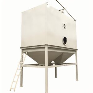
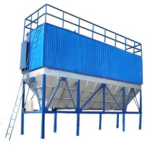
Understanding Pulse Jet Dust Collectors
The first time I witnessed an efficiently operating pulse jet dust collector was at a woodworking facility in Michigan. What struck me wasn’t just the clean air inside the massive production floor, but the methodical rhythm of the cleaning pulses—a technological symphony that kept operations running smoothly without interruption.
Pulse jet dust collectors represent one of the most efficient and widely used dust collection systems in modern industrial settings. These systems employ a continuous cleaning mechanism that allows for uninterrupted operation while maintaining consistent airflow and pressure levels. Unlike older bag-shaking or reverse-air collectors that require periodic downtime, pulse jet technology uses short bursts of compressed air to clean filter media while the system remains operational.
At their core, these systems consist of several key components that work in harmony. The filter housing contains multiple filter elements—typically bags or cartridges—arranged in rows or compartments. A compressed air delivery system connects to a series of manifolds and pulse valves that direct short bursts of high-pressure air into the filters. This momentary reverse airflow dislodges accumulated dust from the outer surface of the filters, allowing it to fall into a collection hopper below.
The timing of these cleaning pulses is managed by a sophisticated control system that can operate on preset intervals or respond to pressure differential readings. This intelligent approach to filter cleaning optimizes energy usage while maintaining consistent air quality.
“The efficiency of a pulse jet system ultimately depends on its installation,” explains Daniel Ramirez, a dust collection specialist I consulted while researching this article. “Poor installation can undermine even the most advanced collector design.”
Understanding the fundamental principles behind pulse jet dust collector technology before beginning installation provides crucial context for the technical decisions you’ll need to make throughout the process. The system’s efficiency, maintenance requirements, and operational costs will all be significantly influenced by how meticulously you approach the installation process.
Pre-Installation Considerations
Before breaking ground or ordering equipment, several critical pre-installation factors must be thoroughly evaluated. I’ve seen hastily planned installations lead to expensive modifications, compliance issues, and suboptimal performance. Taking time at this stage pays dividends throughout the system’s operational life.
Site Assessment and System Sizing
The first question isn’t how to install a pulse jet dust collector, but rather what specific collector configuration suits your application. Start with a comprehensive dust analysis that identifies:
- Dust characteristics (particle size, shape, abrasiveness)
- Combustibility concerns (Kst values and explosion potential)
- Moisture content and chemical properties
- Temperature ranges
Your site’s physical constraints will significantly impact installation options. Measure clear heights, available floor space, and access points for maintenance. Don’t forget to account for weather conditions if installing outdoors—I once worked with a facility in Minnesota that had to completely redesign their installation plan to accommodate heavy snow loads and extreme temperature fluctuations.
System sizing must be calculated based on several factors:
| Parameter | Typical Range | Considerations |
|---|---|---|
| Air-to-cloth ratio | 4:1 to 7:1 | Lower for challenging dusts |
| Filter media | Various options | Match to dust properties |
| Pressure drop | 3-6″ WG | Higher values reduce efficiency |
| Airflow requirements | Application-specific | Based on capture velocity needs |
Regulatory Compliance
Environmental regulations may dictate emission limits, stack testing requirements, and documentation needs. I recommend consulting with an environmental specialist familiar with local requirements early in the planning process. Some jurisdictions require permits before installation can begin.
Fire and explosion protection standards (particularly NFPA 652 and 654) may impose additional requirements for dust hazard analysis, explosion venting, suppression systems, or isolation devices. These elements must be incorporated into your installation planning from the beginning.
Integration with Existing Systems
If you’re replacing older equipment or integrating with existing ventilation, carefully document connection points, transitions, and control interfaces. Review your facility’s electrical capacity to ensure it can handle the additional load of fan motors, control systems, and ancillary equipment.
Compressed air availability and quality represent another critical consideration. Pulse jet systems require clean, dry compressed air at specific pressure and volume levels. Your existing compressed air system may need upgrades to meet these demands.
One plant manager I worked with decided to save money by using their general-purpose compressed air system for a new dust collector. Within months, contaminated air had damaged the pulse valves, resulting in poor cleaning performance and costly repairs—a perfect example of how cutting corners during pre-installation planning can lead to significant operational issues.
Step 1: Site Preparation
Proper site preparation establishes the foundation—both literally and figuratively—for a successful pulse jet dust collector installation. During a recent metalworking facility project, we had to completely reposition the unit after discovering unmarked underground utilities during foundation work. This costly delay could have been avoided with more thorough site investigation.
Foundation Requirements
Most pulse jet dust collectors require a concrete foundation designed to support both the static weight of the equipment and the dynamic loads created during operation. The foundation should:
- Extend beyond the footprint of the collector by at least 12 inches on all sides
- Be level within ±1/8 inch to prevent structural stress
- Include provisions for anchor bolts positioned according to manufacturer specifications
- Incorporate conduit pathways for electrical and control wiring
- Feature drainage considerations for outdoor installations
For larger systems, consult a structural engineer to ensure the foundation can handle the fully loaded weight, including collected dust and potential snow or wind loads for outdoor installations.
Space Planning and Accessibility
Adequate clearance around the equipment is essential for maintenance activities and operational safety. During a recent installation of a high-efficiency pulse jet dust collector, we specifically designed the layout to allow:
- Full door swing clearance for access to the clean air plenum
- Removal space for filter elements (typically vertical clearance above the unit or horizontal clearance at access doors)
- Workspace around electrical panels (minimum 3 feet, per electrical codes)
- Access to compressed air components for maintenance
- Clearance for dust removal from the hopper and container handling
Accessibility isn’t just about maintenance—it also affects operational efficiency. Position control panels where operators can easily monitor system performance, and ensure pressure gauges are visible during normal operation.
Utility Connections
Identify and prepare all required utility connections before equipment arrival:
- Electrical service adequately sized for all motors and controls
- Compressed air supply lines with appropriate pressure and volume capacity
- Water lines if required for specific dust handling needs
- Network connections for advanced monitoring systems
For outdoor installations, underground utilities should be clearly marked and protected during foundation work. Weatherproofing considerations become essential for all connections and junction boxes.
I’ve found that detailed site preparation checklists help prevent overlooked details. Each installation presents unique challenges, but thorough planning at this stage significantly reduces complications during later phases of the project.
Step 2: Component Assembly
With site preparation complete, the next phase involves assembling the collector’s major components. This step requires careful attention to detail and typically follows a specific sequence established by the manufacturer. During a recent installation for a pharmaceutical processing facility, we learned that deviating from the recommended assembly sequence created alignment problems that took days to correct.
Housing Assembly
The collector housing serves as the structural backbone of the system. Most modern pulse jet collectors ship partially disassembled to facilitate transportation. Begin by:
- Identifying all housing components and hardware using the manufacturer’s assembly drawings
- Inspecting all parts for shipping damage before assembly begins
- Setting up the hopper section first, ensuring it’s perfectly level
- Installing the tube sheet (the divider between clean and dirty air chambers)
- Attaching sidewalls, maintaining square and plumb alignment
- Installing the clean air plenum on top
Proper sealing between components prevents dust leakage and air infiltration. Apply specified gaskets and sealants between flanged connections, and torque all fasteners to manufacturer specifications using a calibrated torque wrench. This isn’t a place for shortcuts—uneven tightening can create air leaks that compromise performance.
Filter Media Installation
The filter elements—whether bags, cartridges, or pleated media—require careful handling during installation:
| Filter Type | Installation Considerations | Typical Lifespan |
|---|---|---|
| Bag filters with cages | Insert cage first, then carefully fit bag over cage and secure to tube sheet | 1-3 years depending on application |
| Cartridge filters | Align gasket properly, ensure secure seating against tube sheet | 2-4 years in standard applications |
| Pleated bag filters | Avoid crimping or folding during insertion, verify proper sealing | 1.5-3 years in typical environments |
“One of the most common mistakes I see is improper filter tensioning during installation,” notes Marta Jimenez, a dust collection maintenance supervisor I consulted. “This leads to premature wear and reduced collection efficiency, sometimes cutting filter life in half.”
For bottom-load designs, work from one side to the other methodically. For top-load designs, carefully follow the specified loading pattern to maintain stability during installation. Document filter installation dates either on the unit itself or in maintenance records to establish replacement schedules.
Pulse System Assembly
The pulse cleaning system consists of several interconnected components:
- Install the compressed air manifold (header pipe) according to alignment specifications
- Mount pulse valves at designated locations on the manifold
- Connect pulse pipes or venturis that direct air into filter elements
- Install the electronic controller that sequences the cleaning pulses
Ensure all pneumatic connections are properly sealed and tested for leaks before proceeding. The pulse system operates at high pressure, and even small leaks can significantly reduce cleaning effectiveness while wasting energy.
During assembly, maintain cleanliness of all components. Foreign material in pulse valves or air pathways can cause malfunctions or damage filters. I typically recommend covering openings until final connections are made and flushing compressed air lines before connecting them to the pulse system.
Step 3: Installing the Filtration System
The filtration system lies at the heart of your pulse jet dust collector, directly impacting collection efficiency, pressure drop, and operational costs. During a recent cement plant installation, choosing the wrong filter media resulted in excessive pressure drop and poor cleaning. We had to replace all filters within three months—an expensive lesson in the importance of filtration system details.
Filter Media Selection
Selecting appropriate filter media involves balancing several factors:
- Dust characteristics (particle size, abrasiveness, moisture content)
- Temperature considerations
- Chemical compatibility
- Required filtration efficiency
- Fire and explosion concerns
The table below highlights common filter media options and their applications:
| Media Type | Best Applications | Limitations | Efficiency Range |
|---|---|---|---|
| Polyester | General dust collection, moderate temperatures | Not suitable for hydrolysis conditions or temperatures above 275°F | 99-99.9% |
| PTFE membrane | Fine particulate, high-efficiency needs | Higher cost, requires careful handling | 99.99%+ |
| Fiberglass | High-temperature applications | Less durable with abrasive dusts | 99-99.9% |
| BHA Preveil | Advanced filtration needs, food-grade applications | Premium price point | 99.99%+ |
| Aramid blends | Abrasive applications with moderate temperatures | Higher cost than standard polyester | 99-99.9% |
“Filter media selection represents the most critical decision in the entire installation process,” emphasizes Dr. Elena Kowalski, an industrial hygienist I interviewed. “It determines not only initial performance but also long-term operational costs and compliance capabilities.”
Filter Installation Procedure
Whether installing bag filters or cartridges, the procedure requires careful attention to prevent damage and ensure proper seating:
For bag filters:
- Inspect each filter cage for bends or damage before installation
- Insert the cage into the tube sheet opening
- Carefully slide the filter bag over the cage, avoiding tears or punctures
- Secure the bag to the tube sheet using the specified attachment mechanism (snap band, double beaded gasket, etc.)
- Verify proper tension according to manufacturer specifications
For cartridge filters:
- Inspect the gasket for damage or irregularities
- Align the cartridge with the mounting location
- Insert and rotate to engage locking mechanism or tighten hardware
- Verify proper seating and gasket compression
Cross-contamination between clean and dirty air sections occurs if filters aren’t properly sealed against the tube sheet. I always recommend performing a visual inspection from the clean air plenum using a flashlight to check for light leaks around filter connections before proceeding.
Pulse Cleaning System Setup
The pulse cleaning system requires precise setup to function effectively:
- Verify alignment of pulse pipes with filter openings
- Set initial pulse duration (typically 100-150 milliseconds)
- Establish cleaning frequency based on application (time-based or pressure-based)
- Confirm compressed air pressure at the header (typically 90-100 psi)
Modern pulse jet dust collector systems often include adjustable pulse parameters. Initial settings should follow manufacturer recommendations, with fine-tuning during commissioning based on actual operating conditions.
I’ve found that documenting baseline settings after optimization creates a valuable reference for maintenance personnel when troubleshooting future performance issues.
Step 4: Ductwork Installation
Ductwork design and installation significantly impact a dust collector’s performance. I once consulted on a woodworking facility where improper ductwork reduced actual airflow to less than 60% of design capacity, creating both safety and productivity issues throughout the plant.
Ductwork Design Principles
Effective ductwork for a pulse jet dust collector follows several key principles:
- Maintain minimum transport velocity to prevent dust settlement
- Design for balanced airflow across multiple pickup points
- Minimize turbulence and pressure losses
- Provide access for inspection and cleaning
- Include proper blast gates and balancing dampers
Transport velocities vary by material type:
| Material Type | Minimum Transport Velocity (FPM) |
|---|---|
| Fine, dry dusts | 3,500-4,000 |
| Medium-weight dusts | 4,000-4,500 |
| Heavy or moist particles | 4,500-5,000 |
| Fibrous materials | 5,000-6,000 |
“Properly sized ductwork is absolutely essential when installing a pulse jet dust collector,” notes James Chen, an industrial ventilation engineer I consulted. “Undersized ducts create excessive pressure losses and velocity issues, while oversized ducts waste material and increase system cost unnecessarily.”
Installation Best Practices
When installing ductwork:
- Support horizontal runs at intervals not exceeding 10 feet
- Install flexible connections to isolate vibration between the fan and ductwork
- Seal all joints with appropriate materials (silicone, duct sealant, or gaskets)
- Install ductwork with the airflow direction indicated on components
- Provide adequate clearance from walls and obstructions for inspection
- Incorporate proper transitions to minimize pressure losses
Long radius elbows (centerline radius at least 1.5 times the duct diameter) significantly reduce pressure losses compared to short radius or segmented elbows. Where space constraints require tight turns, turning vanes help maintain efficient airflow.
For abrasive materials, consider wear-resistant elbows or wear plates at impact points. During one mineral processing installation, we installed replaceable wear plates at key transition points, extending the ductwork lifespan significantly.
Inlet and Outlet Considerations
The collector inlet requires special attention:
- Position the inlet to distribute airflow evenly across filter elements
- Install a diffuser or baffle plate for proper dust distribution
- Maintain adequate distance between the inlet and filters to allow dust to decelerate
- Consider inlet design based on dust characteristics (tangential vs. radial entry)
For the clean air outlet:
- Size the outlet duct to maintain appropriate velocity
- Install proper weather protection for outdoor exhausts
- Include required emission testing ports per regulatory standards
- Consider noise attenuation if needed
For systems returning air to the building, terminal devices should distribute air away from work areas and prevent drafts. I typically recommend discharge locations at least 10 feet above floor level and away from workstations.
Step 5: Control System Setup
The control system is the brain of your pulse jet dust collector, managing everything from basic operation to sophisticated diagnostic functions. During a cement plant installation last year, implementing an advanced control system with pressure-based cleaning logic reduced compressed air consumption by 47% compared to their previous time-based system.
Control Panel Installation
Begin by mounting the control panel in an accessible location that meets these requirements:
- Protected from dust, moisture, and extreme temperatures
- Meets electrical code clearance requirements (typically 3-4 feet of clear space)
- Visible to operators during normal facility operation
- Protected from physical damage by equipment or materials handling
Connections to the panel should follow manufacturer specifications and local electrical codes. Typical connections include:
- Main power supply (verify voltage and phase requirements)
- Fan motor connections
- Compressed air header and pulse valve wiring
- Pressure differential sensors
- Hopper level indicators
- Auxiliary equipment interfaces (rotary airlock, screw conveyor, etc.)
Always use appropriate conduit, seals, and strain relief for all connections. For outdoor installations, weatherproof enclosures and connections prevent moisture ingress and related electrical failures.
Programming Cleaning Parameters
Modern industrial dust collector systems offer several cleaning logic options:
- Time-based cleaning: Pulses filters at fixed intervals regardless of dust load
- Pressure-based cleaning: Initiates cleaning cycles when pressure differential reaches preset thresholds
- Hybrid approaches: Combines time and pressure parameters for optimized operation
Initial programming should establish:
- Pulse duration (typically 100-150 milliseconds)
- Pulse interval between valves (typically 3-10 seconds)
- Pressure differential setpoints (if applicable)
- Alarm thresholds for high differential pressure
- Fan startup/shutdown sequences
“The control system setup phase is where you can really optimize performance,” explains Maria Dominguez, an automation specialist I worked with on several complex installations. “Taking time to fine-tune parameters based on actual operating conditions rather than just using default settings can reduce compressed air consumption by 15-30% while maintaining or improving cleaning effectiveness.”
Motor Controls and Safety Circuits
Fan motor controls require careful attention to prevent damage and ensure safe operation:
- Verify motor rotation direction before extended operation
- Implement soft-start or VFD technology for larger motors to reduce startup current
- Configure proper overload protection based on motor specifications
- Establish safety interlocks with other system components
Safety circuits should include emergency stop functions, access door interlocks, and equipment protection features. For combustible dust applications, integrate safety controls with explosion protection systems according to NFPA and other applicable standards.
I recommend documenting all control setpoints and programming details for future reference. When system modifications or troubleshooting become necessary, this documentation provides invaluable baseline information.
Step 6: Compressed Air System Connection
The compressed air system delivers the energy needed for filter cleaning, making it a critical component in pulse jet collector performance. During a manufacturing plant installation where we connected to an existing compressed air system, insufficient capacity during peak demand periods resulted in inadequate cleaning and rapidly increasing differential pressure.
Compressed Air Requirements
Pulse jet systems typically require:
- Operating pressure of 90-100 psi at the header
- Clean, dry air (maximum -40°F pressure dew point)
- Oil content less than 1 ppm
- Adequate volume to handle peak pulse demands
The required compressed air volume depends on:
| Factor | Impact on Air Consumption |
|---|---|
| Number of pulse valves | Direct relationship – more valves require more air |
| Valve size (typically 3/4″ to 2″) | Larger valves consume more air per pulse |
| Pulse duration | Longer pulses consume more air |
| Cleaning frequency | More frequent pulses increase average consumption |
For most systems, I recommend calculating peak and average air consumption, then adding 25-30% capacity margin to accommodate potential future needs or system variations.
Air Preparation and Piping
Install an air preparation system that includes:
- Particulate filtration (typically 5 micron or better)
- Coalescing filtration for oil removal
- Air drying equipment (refrigerated or desiccant type)
- Pressure regulation
- Condensate management system
The compressed air piping should be sized to minimize pressure drop between the air supply and the pulse header. For most installations, I recommend:
- Main supply lines sized for velocity under 30 ft/second at peak flow
- Minimal use of restrictive fittings like elbows and tees
- Gentle sloping of horizontal runs to allow condensate drainage
- Installation of appropriate isolation valves and drains
- Insulation in freezing environments
“Undersized compressed air piping is one of the most common installation mistakes I encounter,” says Thomas Wiśniewski, a compressed air specialist I consult with regularly. “A pressure drop of just 5 psi at the header can reduce cleaning effectiveness by 10-15%, yet many installers try to economize on piping diameter.”
Header and Pulse Valve Connections
The compressed air header requires careful installation:
- Mount securely to prevent vibration during pulsing
- Install in the orientation specified by the manufacturer
- Ensure proper alignment with pulse pipes or venturis
- Configure condensate drainage if required by the design
Connections to individual pulse valves should:
- Use appropriate fittings without restricting airflow
- Include flexible connections where needed for maintenance access
- Maintain proper alignment between valves and filter elements
After completing connections, pressure test the entire system for leaks before operation. Even small air leaks can significantly impact system performance and operating costs over time.
Step 7: Testing and Commissioning
Thorough testing and commissioning transforms a physically complete installation into a properly functioning system. During a recent dust collection system installation at a pharmaceutical facility, our commissioning process identified several issues that would have significantly impacted performance had they not been addressed before handover.
Initial System Inspection
Before energizing any components, conduct a comprehensive inspection including:
- Verification that all shipping materials and restraints have been removed
- Confirmation that all access doors and inspection ports are properly secured
- Checking rotation arrows on fans match intended direction
- Verification of proper filter installation and seating
- Confirmation that all electrical connections are secure and properly terminated
- Inspection of ductwork for any debris or foreign materials
Document this inspection process with a detailed checklist signed by both installation and commissioning personnel. This creates accountability and ensures nothing is overlooked.
Fan and Airflow Testing
Start with fan testing:
- Momentarily energize the fan to verify rotation direction
- Perform a full startup and check for unusual vibration or noise
- Measure and record motor amperage under no-load conditions
- Gradually introduce system airflow by opening dampers incrementally
- Measure and record system static pressure at key points
- Verify airflow at collection points using an anemometer or pitot tube
- Balance airflow across multiple pickup points using dampers
Capture baseline measurements of:
- Static pressure at the collector inlet
- Differential pressure across filters
- Fan amperage under full load
- Airflow velocities at critical points
These measurements establish performance benchmarks for future comparison during maintenance evaluations.
Pulse System Testing
Test the cleaning system thoroughly:
- Verify compressed air pressure at the header (typically 90-100 psi)
- Manually trigger each pulse valve to confirm proper operation
- Check pulse timing and sequencing through multiple cycles
- Verify pressure gauge readings during operation
- Listen for abnormal sounds during pulse operation
- Check for proper filter movement during cleaning pulses
“The commissioning phase often reveals subtle installation issues that might not be immediately obvious,” notes Paulo Rodriguez, a commissioning specialist I’ve collaborated with. “For example, during one startup, we discovered uneven cleaning performance caused by a partially blocked compressed air line that passed all standard pressure tests but couldn’t deliver adequate volume during actual pulsing.”
Control System Verification
Test all control functions including:
- Normal startup and shutdown sequences
- Emergency stop functionality
- Alarm conditions and responses
- Differential pressure monitoring and response
- Interlock operation with connected equipment
- Remote monitoring capabilities (if installed)
- Automated cleaning cycle operation
For pressure-based cleaning systems, artificially create pressure differential conditions to verify proper response. For time-based systems, confirm proper interval timing across multiple cycles.
Document all final settings, including:
- Pressure differential setpoints
- Pulse durations
- Cleaning frequency parameters
- Alarm thresholds
- Timer settings for auxiliary equipment
This documentation becomes invaluable for maintenance personnel and future system modifications.
Maintenance Best Practices
Even the most meticulously installed pulse jet dust collector requires proper maintenance to maintain performance. I’ve seen perfectly designed systems deteriorate rapidly due to neglected maintenance routines. Establishing these practices during commissioning sets the foundation for long-term reliability.
Establishing Maintenance Schedules
Create a comprehensive maintenance schedule based on:
- Manufacturer recommendations
- Dust characteristics and loading
- Operating hours and conditions
- Regulatory requirements
- Previous experience with similar equipment
A typical maintenance schedule includes:
| Interval | Maintenance Tasks |
|---|---|
| Daily | Visual inspection, pressure differential recording, brief operation check |
| Weekly | Compressed air system inspection, dust discharge system check, leak inspection |
| Monthly | Filter inspection (if possible without shutdown), control system test, motor and drive inspection |
| Quarterly | Thorough internal inspection, pulse valve examination, ductwork check |
| Annually | Comprehensive system inspection, performance testing, control system validation |
Document this schedule and assign specific responsibilities to maintenance personnel. I recommend creating detailed procedure documents for complex tasks to ensure consistency regardless of who performs the maintenance.
Filter Maintenance and Replacement
Filter elements require special attention:
- Establish baseline pressure drop readings when filters are new
- Define trigger points for replacement based on pressure differential increases
- Document filter replacement dates and performance observations
- Implement proper procedures for safe filter removal and disposal
- Train maintenance personnel on proper handling of replacement filters
“Filter replacement procedures often determine whether you’ll achieve optimal performance from new filters,” explains Samantha Torres, a maintenance supervisor I interviewed. “Improper handling during installation can significantly reduce filter life and efficiency.”
For systems handling hazardous dusts, develop specific procedures for safe filter change-out that protect both workers and the facility environment.
Monitoring System Performance
Implement ongoing monitoring practices:
- Track differential pressure trends over time
- Monitor fan amperage and compare to baseline values
- Regularly inspect dust discharge systems for proper operation
- Check compressed air quality and pressure consistently
- Review any unusual operating patterns or alarm conditions
Modern systems often include data logging capabilities that facilitate trend analysis. Even basic manual logging provides valuable information when tracked consistently over time.
I recommend creating a central documentation location where all maintenance activities, performance observations, and repair work are recorded. This historical record proves invaluable for troubleshooting and planning preventive maintenance.
Troubleshooting Common Installation Issues
Even with careful planning and execution, installation challenges can arise. Having addressed numerous issues across dozens of installations, I’ve identified several common problems and their solutions.
Excessive Pressure Drop
When pressure drop exceeds expected values, investigate:
- Improper filter media selection: Reconsider filter media based on actual dust characteristics rather than general specifications
- Insufficient filter cleaning: Check compressed air pressure, pulse duration, and frequency
- Air entrapment in the hopper: Verify proper dust discharge system operation
- Ductwork restrictions: Inspect for buildup, collapsed sections, or closed dampers
- Uneven airflow distribution: Check for proper inlet design and baffle configuration
During a paper mill installation, we encountered unexpectedly high pressure drop despite proper filter selection. Investigation revealed that the inlet design was causing uneven dust loading on filters, with some receiving much heavier loading than others. Modifying the inlet baffle system resolved the issue by distributing dust more evenly.
Inadequate Dust Capture
If dust escapes collection points:
- Insufficient airflow: Verify fan performance and system design calculations
- Poorly designed capture hoods: Redesign based on capture velocity requirements
- Air infiltration elsewhere in the system: Locate and seal leaks in ductwork
- Improper system balancing: Adjust dampers to direct appropriate airflow to each collection point
- Changed process conditions: Reassess if production parameters have changed since design
“Most capture problems stem from fundamental design issues rather than equipment failures,” notes ventilation engineer Marco Ferreira during a consultation. “Successful troubleshooting requires a systematic approach that begins with airflow measurements at each capture point.”
Pulse System Problems
For pulse cleaning issues:
- Inconsistent pulse performance: Check for compressed air supply fluctuations or restrictions
- Pulse valve failures: Inspect for contamination, wear, or electrical problems
- Poor pulse effectiveness: Verify alignment between pulse pipes and filter elements
- Compressed air quality issues: Test for excessive moisture or oil contamination
- Control system timing problems: Review and adjust pulse duration and sequencing
During one food processing facility installation, intermittent pulse performance was traced to an undersized compressed air supply line that couldn’t maintain pressure during multiple consecutive pulses. Upgrading the supply line diameter resolved the issue completely.
Structural and Mechanical Issues
Address mechanical concerns promptly:
- Excessive vibration: Check for proper foundation mounting, fan balance, or ductwork support
- Housing leaks: Locate and seal with appropriate materials based on system pressure
- Access difficulties: Modify platforms or ladders to improve maintenance accessibility
- Weather-related problems: Implement appropriate protection for outdoor components
- Noise issues: Add insulation, isolation mounts, or silencers as needed
Documenting troubleshooting processes creates valuable reference material for future issues. Include initial symptoms, diagnostic steps, findings, and resolution details for each significant problem addressed.
The most successful installations involve close collaboration between design engineers, installation contractors, and facility personnel. This partnership approach ensures that everyone understands both the technical requirements and operational considerations that influence system performance.
Frequently Asked Questions of how to install pulse jet dust collector
Q: What are the basic steps to follow when installing a pulse jet dust collector?
A: Installing a pulse jet dust collector involves several critical steps. Start by carefully lifting and assembling the equipment, ensuring all components are securely connected and sealed. Ensure that filter bags are installed properly within cages and that all connections are airtight to prevent air leakage. Finally, connect the compressed air system for pulse cleaning.
Q: How do I ensure proper air tightness during the installation of a pulse jet dust collector?
A: To achieve proper air tightness, ensure that all connections are sealed using appropriate materials like gaskets or sealing compounds. Welding may also be required for flanged connections. Regularly inspect for any air leaks and address them promptly to maintain optimal system performance.
Q: What precautions should I take when handling filter bags during installation?
A: Filter bags are delicate and require careful handling to prevent damage. Avoid touching the bags with sharp objects, and ensure they are not scraped against the tube sheet during installation. Properly seating the snap-band and aligning the cage within the bag are crucial for effective dust collection.
Q: How important is maintenance after installing a pulse jet dust collector?
A: Regular maintenance is essential to extend the lifespan and efficiency of your pulse jet dust collector. This includes routine inspections for leaks, cleaning or replacing filter bags as needed, and ensuring that the compressed air system operates correctly.
Q: What role does compressed air play in the operation of a pulse jet dust collector?
A: Compressed air is vital for the pulse cleaning process, which involves high-pressure jets of air to clean the filter media. Ensure the air is clean and dry to prevent damage to the system. A well-maintained air supply will enhance the overall performance and longevity of the dust collector.
Q: Are there specific safety precautions I should take during the installation process?
A: Always follow safety guidelines when installing a pulse jet dust collector, especially when working within confined spaces. Ensure that electrical components are installed by qualified personnel, and adhere to OSHA guidelines for safe working practices. Proper grounding and protection from transient spikes are also crucial for electrical safety.
External Resources
- Installation, Operation & Maintenance Manual – Provides comprehensive guidelines for installing, operating, and maintaining pulse jet dust collectors, including important steps for filter bag assembly and system start-up.
- Tips of Installation of Pulse Jet Bag Filter/Dust Collector/Baghouse – Offers practical installation steps and precautions for pulse jet bag filters to ensure proper sealing and prevent damage during the process.
- Pulse Jet Dust Collector Manual – Vayuvents – Covers the design and operation of pulse jet dust collectors, highlighting automatic cleaning processes and the importance of air tightness during installation.
- Camcorp’s Pulse Jet Dust Collector Tips – Shares insights on common installation mistakes and troubleshooting techniques for maintaining efficient dust collection systems.
- Air Pollution Control Equipment Installation and Maintenance – Although not specific to pulse jet collectors, it provides general guidelines for installing and maintaining air pollution control equipment that can be applied to similar systems.
- Dust Collection Systems Installation and Maintenance Best Practices – Offers industry-wide best practices for dust collection systems installation, including tips that can apply to pulse jet collectors for optimal performance.
