Make-up air near a dust-capture workstation needs to be documented before equipment is sized or installed, because the collector operates within the building’s air balance—not as a stand-alone device. The key variables are where replacement air enters the space, which supply and exhaust systems run simultaneously, and which organization owns each part of the arrangement. Get those on paper first, and the engineering conversation with a supplier becomes specific rather than speculative.
Identify supply and exhaust operating states
Every dust-capture workstation that exhausts air to the outside or to a filtered discharge removes air from the building, and something has to replace it. That replacement comes from somewhere—a dedicated make-up air unit, the general HVAC supply, open doors, or some combination—and the first documentation task is to list each source alongside the exhaust equipment it coexists with.
Start with what is already operating when grinding runs. Walk the space and note every supply outlet, return grille, exhaust fan, and door or louver that is normally open during the shift. A collector quotation prepared without this inventory treats the installation as if it sits in an infinite, still room. It does not.
Сопутствующие товары
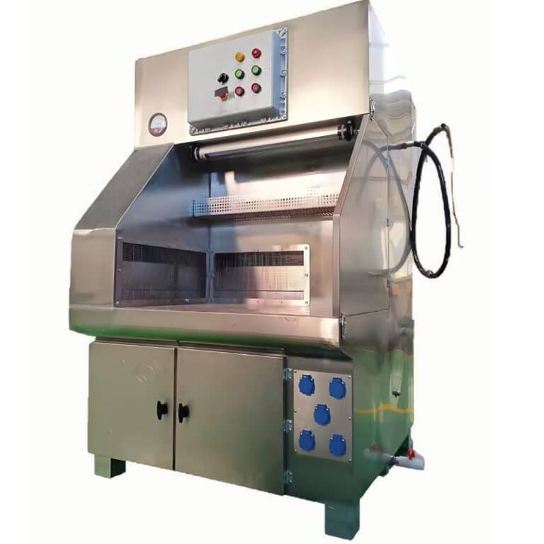
- Промышленный стол сухого/мокрого помола с пригрузом — Review the official workstation product entry when matching the loaded work envelope and the offered dry or wet configuration; confirm the actual quoted arrangement.
- Промышленный портативный пылесборник — Consider a portable source-capture alternative when the task moves or a fixed station is unsuitable; compare the actual hose, working position and installed duty.
- Картриджный пылесборник — Review a cartridge-collector route for the remaining dry-dust collection duty, subject to material and configuration review.
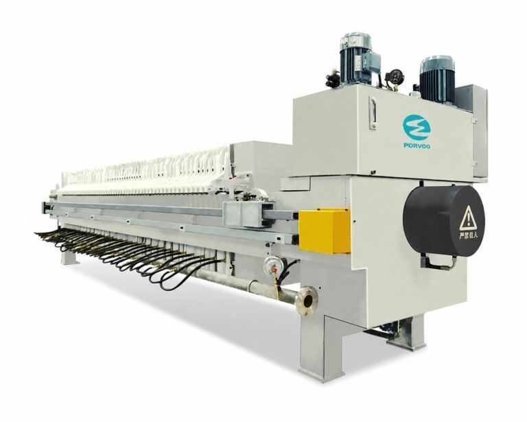
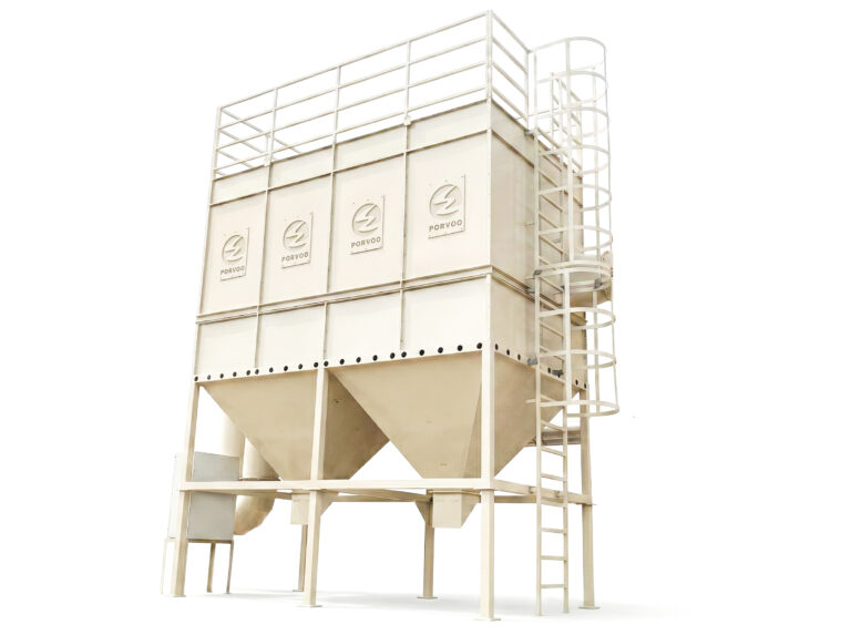
- Импульсный струйный пылеуловитель — Review a pulse-jet collector as a possible downstream or central collection interface; confirm material suitability and the actual quoted duty.
- Dust Collection & Air Pollution Control — See the official collection family when comparing station-level and wider system options without assuming every configuration is included.
The capture unit operates within a building air balance rather than in isolation; a quotation that ignores the existing supply and exhaust picture may leave the installation short of replacement air.
Operating states change—and that matters as much as the steady-state layout. If a loading dock door is open in summer and closed in winter, air enters and leaves the space by different paths in each season. If a second exhaust fan runs only during peak production, the pressure balance shifts when it starts. Record those transitions alongside your observations of capture performance, because a measurement taken under closed-door conditions can describe a situation that never repeats itself during normal production. The only exception is when the facility formally operates with the building in a single, fixed state and the alternative is contractually outside scope.
Capture what you have:
- Supply outlets: type (diffuser, slot, overhead unit heater), rated airflow where known, discharge direction
- Exhaust equipment in simultaneous service: existing collectors, general exhaust fans, roof vents
- Variable states: doors, operable windows, supplemental fans, and the production conditions that govern each state
- Known imbalances: spaces that run at measurable positive or negative pressure under any operating condition
This list becomes the baseline against which the new workstation is added.
Map air direction at the working position
Air direction at the grinding position is where abstract building-balance figures become a practical capture problem. Local air movement can redirect a dust cloud toward or away from the hood, and the documentation should show both the source of that movement and the path it creates relative to the operator.
Conditions that change the review
| Наблюдаемое состояние | Review action | Decision reason and boundary |
|---|---|---|
| Supply outlets are close to grinding | Sketch their discharge direction relative to the source and operator | Local air movement can alter the contaminant path the hood must control Exception: The proposed outlet is relocated before the final layout is evaluated. |
| Doors or fans change state during a shift | Record those states alongside observations of capture | An observation under closed-door conditions may not represent the normal production arrangement Exception: The operating scope formally excludes the alternative state. |
Supply outlets near the workstation deserve particular attention. A diffuser directly above a grinding table may discharge downward across the operator’s breathing zone before the hood can capture the plume. An overhead unit heater aimed at the work area from the side can push dust laterally rather than into the hood face. The direction of discharge matters as much as its volume, and a simple sketch—drawn to approximate scale, showing the outlet location, its throw direction, and the grinding point—captures this more reliably than a written description.
The sketch should identify:
- Each supply outlet within roughly three to five metres of the workstation, with its discharge angle marked
- The grinding or processing point where dust is generated
- The operator’s standing or seated position
- The hood face or capture point and its orientation
- Any obstruction (a shelf, a machine guard, a wall) that could deflect air before it reaches the hood
If a supply outlet is already proposed for relocation before the layout is finalized, its current position need not drive the analysis—document the confirmed future position instead, and note the pending change so it is visible during design review.
Consider a project where a ceramic grinding cell has a unit heater on the north wall aimed southeast across the table. The grinder works facing south. A new downdraft grinding table placed at that position would receive airflow across the work surface from the wrong direction, reducing capture efficiency even at correct extraction volumes. Sketching the arrangement before specifying the hood type or airflow reveals the conflict while the layout is still adjustable.
Air direction also shifts with operating state. A supply system running at full capacity on a cold morning creates a different local pattern than the same system throttled back in summer. If the workstation will be used year-round, the documentation should include at least two states: one where supply airflow is highest and one where it is lowest.
Allocate building and equipment interfaces
A dust-capture installation crosses an ownership boundary: the collector and its ducting typically fall within the equipment supplier’s scope, while the building supply—the make-up air unit, the ductwork feeding it, and its controls—typically remains a facility responsibility. Leaving that boundary undefined is a common source of project gaps, where both parties assume the other has covered replacement air.
Where replacement air is a facility responsibility, name its connection point, operating coordination, and responsible party in the interface list before the quotation is issued.
Build an interface list with four columns: the system or component, its owner (equipment supplier or facility), the connection or coordination point where the two meet, and any operating interlock or sequencing requirement. A collector exhaust fan that starts on a signal from the facility control system, or a make-up air unit that must open its damper before the extraction fan ramps up—these are coordination points that need to be explicit, not assumed.
Where a collector quotation is under review, check whether building supply work appears anywhere in its scope. It usually does not. That is not a deficiency in the quotation; it reflects a standard scope division. The deficiency is assuming the work will appear somewhere without confirming it. If the confirmed quotation expressly includes make-up air supply work, that division changes—but verify it in writing rather than by inference.
The interface list should address:
- Make-up air supply: source, rated airflow, connection location (direct to workstation or to general space), responsible party
- Electrical and controls: starter or VFD ownership, interlock wiring, BAS integration if any
- Structural and architectural: penetrations, stack or duct support, roof or wall curbs
- Commissioning access: who can adjust supply airflow, what access is needed, who signs off
When a supplier is asked to provide additional extraction airflow—say, upgrading a collector to a higher-capacity model—ask explicitly how the change affects both the source capture arrangement and the replacement-air requirement together. More extraction draws more air from the building; if the supply side does not scale with it, the net result can be a larger pressure deficit rather than better capture. That is not a reason to avoid the upgrade; it is a reason to scope the supply change alongside it.
Related Reading
- Контрольный список для запроса предложений на стол для измельчения с нисходящим потоком — Prepare the working-envelope and operating information for a station enquiry; compare it with the exact task described here.
- Статическое давление и потери в воздуховодах в системах пылеудаления рабочих мест: почему номинальные значения в кубических футах в минуту (CFM) вводят в заблуждение — Review the installed-flow discussion while comparing quotation duties rather than relying on a nameplate figure.
- Реестр документации по пылесборнику: что необходимо монтажным и эксплуатационным бригадам при сдаче объекта — Prepare the document handover after the layout and duty are confirmed, with equipment and site responsibilities recorded.
Verify the combined ventilation arrangement
Verification is useful only for the configuration it documents, which means every measurement needs a recorded operating state to be worth anything at commissioning. A capture velocity reading taken with the make-up air unit off and the loading door open describes a configuration that may not match any normal production condition.
Before starting a final check, confirm and record:
- Supply system state: which units are running, at what setpoint or airflow, with which damper positions
- Extraction system state: which collectors or exhaust fans are active, at what capacity
- Process task: what material is being ground or processed, at what feed rate
- Measurement method: instrument type, measurement location, and who is conducting the check
Commissioning evidence is useful only for its documented configuration and operating conditions; a reading without a recorded state cannot be used to confirm that the installation meets design intent.
With those four items fixed, the measurement result is interpretable. Without them, it is a number.
The sequence matters too. Verify the supply-side air delivery first—confirm that the make-up air unit reaches its design airflow before testing capture at the workstation. If the supply side is short, the extraction system will be drawing from the building fabric: through gaps, cold joints, and uncontrolled pathways. Capture performance measured under those conditions will not repeat when the supply deficiency is corrected.
Where the facility uses a building automation system, check that the interlock logic between supply and extraction is active and sequenced correctly during the test. A BAS that starts the collector before the make-up air damper opens creates a brief but significant pressure dip; in a space with silica-generating processes, that transient matters.
PORVOO’s downdraft grinding tables and ducted collector installations are designed to operate within a defined supply-air arrangement, and the documentation prepared through the steps above is what connects the equipment performance specification to the actual building condition. Before a supplier conversation, have the building air balance baseline, the local air-direction sketch, the interface list with ownership assigned, and the intended operating states for both summer and winter conditions ready to share.
References
- UK HSE HSG258 Controlling Airborne Contaminants at Work — Compare the process, moving source and operator needs with the proposed hood and complete ventilation system; UK guidance, without transferable example values or legal duties.
- OSHA Technical Manual Section III Chapter 3 – Ventilation Investigation and Local Exhaust Systems — Check installed airflow, pressure, fan and filter state with the operating configuration recorded; US technical guidance, without universal design values.
- NIOSH HHE 2015-0180-3261 – Downdraft Table Capture Ergonomics Filter Change and Noise — Review the effect of source height and table geometry and the filter-removal handling boundary; one aluminum-sanding investigation, without transferable measured results.
- UK HSE Commission Your Local Exhaust Ventilation System — Identify configuration, operating conditions and test records needed to interpret an installed-system check; UK commissioning guidance, without assigning contractual duties.
Часто задаваемые вопросы
Q: Is an open door a dependable make-up-air specification?
A: No. Record it as an operating condition and identify whether the project actually relies on that state, including who controls it.
Q: Should building supply and extraction be reviewed by different teams?
A: They may have different owners, but share one interface description so outlet direction and operating states are evaluated together.
Q: Can I reuse a capture observation from before a supply outlet moved?
A: Treat the changed outlet as a changed condition. Compare its new direction and operating state before applying the earlier observation.