Выбор пылесборника до определения условий эксплуатации рабочего места — это самый верный способ получить систему, которая пройдет проверку документации, но не оправдает себя в производстве. Видимым признаком этого станет утечка пыли из зоны улавливания уже в первую смену; дорогостоящим признаком станет перепроектирование вытяжного колпака или модернизация пылесборника после монтажа, когда воздуховоды уже закреплены, а фундамент для пылесборника уже залит. Предотвратить это можно, следуя определённой последовательности: сначала определить условия на источнике, затем спроектировать вытяжной колпак, а уже потом выбрать пылесборник — ведь каждое последующее решение зависит от того, что происходит на первых двух этапах. Читатели, которые будут следовать этой последовательности, смогут более точно определить расход воздуха, тип фильтра и ступень пылесборника, не столкнувшись с несоответствием производительности при вводе в эксплуатацию.
Перед выбором оборудования определите источник запыленности на рабочем месте
Выбор коллектора — это конечный результат, а не отправная точка. Прежде чем приступить к расчету параметров любого оборудования, необходимо достаточно подробно задокументировать технологические условия на рабочем месте, чтобы определить, какую задачу фактически решает система пылеудаления. Без этой основы расчеты расхода воздуха сводятся к догадкам, выбор фильтрующих материалов становится произвольным, а конструкция выпускных устройств может оказаться несовместимой с фактически образующейся пылью.
Параметры, определяющие размеры пылесборника, взаимосвязаны. Тип материала и технологический процесс определяют, с какими загрязнениями приходится бороться: мелкой взвешенной пылью, крупными абразивными частицами, искрами или их комбинацией. Объем пыли за смену определяет производительность пылесборника и частоту опорожнения разгрузочного бункера или барабана. Расстояние улавливания — фактическое рабочее расстояние между инструментом оператора или заготовкой и лицевой поверхностью вытяжного колпака в реальных условиях эксплуатации — определяет, сможет ли скорость улавливания у вытяжного колпака реально достигать точки образования пыли. Эти три фактора взаимодействуют между собой: пылесборник, рассчитанный на нужный расход воздуха, но с вытяжным колпаком, расположенным слишком далеко от источника, всё равно не будет работать эффективно.
Графа «Характеристики пыли» в приведенной ниже таблице параметров зачастую остается без должного внимания на этапе разработки технических требований, однако именно она определяет выбор фильтрующего материала, решения по организации технологических этапов, а в случаях работы с горючими или опасными видами пыли — классификацию безопасности всей системы. Короткое видео, снятое во время реальной смены, часто позволяет увидеть условия работы — насколько далеко операторы отходят от вытяжного колпака, насколько интенсивно рассеивается пыль, является ли место образования пыли стационарным или подвижным — которые в письменном описании зачастую остаются незамеченными. Эти наблюдения стоит сделать до окончательного утверждения технических требований.
| Параметр | Почему это важно | Что необходимо уточнить |
|---|---|---|
| Материалы и процесс | Тип технологического процесса определяет требования к системам локализации и особенности поведения пыли (например, при шлифовании металла образуются более тяжелые частицы и искры). | Обрабатываемый материал (металл, дерево и т. д.) и конкретный процесс (шлифование, резка, полировка, шлифование наждаком). |
| Объем пыли за смену | Определяет необходимую производительность коллектора, частоту сброса и нагрузку на фильтр. | Расчетный объем или масса пыли, образующейся за одну смену; укажите, является ли процесс непрерывным или прерывистым. |
| Расстояние до места погрузки | Эффективность улавливания резко снижается с увеличением расстояния; расположение колпака зависит от допустимого расстояния до источника. | Максимальное расстояние от точки генерации до всасывающего колпака в реальных условиях эксплуатации. |
| Количество пунктов сбора | Определяет общий расход воздуха в системе и то, потребуется ли один коллектор или несколько агрегатов. | Количество рабочих мест или пунктов выдачи, которые должны работать одновременно. |
| Характеристики пыли | Эти факторы влияют на выбор фильтрующего материала, требования к безопасности, а также на необходимость предварительной сепарации. | Классификация: взвешенные в воздухе и осевшие, абразивные, липкие, мелкодисперсные, горючие, опасные, чувствительные к влаге. |
| Доступная мощность и требования к фильтрам/сбросу | Гарантирует, что коллектор соответствует установленным на объекте ограничениям по электрооборудованию и отвечает требованиям по выбросам или утилизации. | Доступное напряжение/фаза, требуемая эффективность фильтрации и предпочтительный способ удаления пыли (барабан, мешок, ротационный клапан). |
Пропуск этого этапа документирования неизменно влечет за собой последствия на последующих этапах: при вводе в эксплуатацию результаты измерений скорости улавливания на лицевой поверхности вытяжного колпака оказываются ниже ожидаемых, а первопричина этого кроется в допущениях, сделанных несколькими неделями ранее относительно расстояния улавливания или одновременных точек сбора. Модернизация на данном этапе обходится дороже, чем стоила бы первоначальная оценка.
Пункты приема для шлифования, резки, полировки и шлифования по карте
После документирования условий в источнике загрязнения необходимо определить конструкцию вытяжного колпака и точки забора воздуха, прежде чем рассчитывать расход воздуха в коллекторе. Именно этот этап чаще всего сводят к простому выбору оборудования из каталога, и именно здесь возникают «мёртвые зоны» и неэффективный улавливание загрязнений.
При шлифовании, резке, полировке и зачистке «улавливание у источника» означает размещение точки отбора как можно ближе к месту образования пыли — с помощью вытяжного манипулятора, щелевого колпака, кожуха или прямого подключения к инструменту. Расстояние быстро снижает эффективность улавливания; каждый дополнительный дюйм между точкой образования пыли и лицевой поверхностью колпака увеличивает расход воздуха, необходимый для поддержания той же скорости улавливания. Щелковатые вытяжные колпаки, расположенные близко к источнику, не только повышают надежность улавливания, но и снижают общую потребность в CFM со стороны коллектора, что имеет значительные последствия с точки зрения энергопотребления и затрат в течение всего срока эксплуатации системы. Глава 33 Справочника ASHRAE, посвященная промышленным системам локальной вытяжки, содержит технологические рекомендации по принципам проектирования вытяжных колпаков, включая взаимосвязь между геометрией колпака, скоростью на лицевой поверхности и эффективностью улавливания.
Конструкция вытяжного колпака с прорезями требует правильного учета пяти взаимосвязанных факторов: размеров прорезей, баланса воздушного потока по всей длине колпака, требуемой скорости улавливания для конкретного технологического процесса, оптимизации системы воздуховодов и достаточной производительности коллектора на выходе. Отсутствие хотя бы одного из этих факторов приводит к предсказуемой картине сбоев: вытяжка с «мёртвыми зонами» на одном конце и чрезмерной скоростью на другом; оператор, который бессознательно меняет положение, чтобы чувствовать себя комфортно, но при этом выносит свою работу за пределы зоны улавливания; или ответвление воздуховода, создающее падение давления, которое вентилятор не в состоянии преодолеть.
| Коэффициент проектирования | Требование | Последствия в случае игнорирования |
|---|---|---|
| Ширина и длина паза | Размеры должны соответствовать исходному размеру и расстоянию съемки, чтобы обеспечить равномерную скорость по всей длине щели. | Неравномерная циркуляция воздуха, снижение эффективности улавливания на концах щелей, просачивание пыли мимо вытяжного колпака. |
| Равновесие воздушных потоков вдоль вытяжного колпака | Воздушный поток должен быть сбалансирован, чтобы каждый сегмент щели создавал равномерное всасывание; для этого часто требуется использовать конический воздуховод или регулируемые перегородки. | «Мёртвые зоны», в которых не происходит улова, — локальные участки с высокой скоростью течения, приводящие к потере энергии. |
| Скорость захвата | Скорость в месте образования пыли должна соответствовать минимальному значению, необходимому для данного технологического процесса (например, 100–200 футов в минуту для легкой пыли). | Пылевое облако не попадает в вытяжной колпак; уровень воздействия на оператора повышается. |
| Оптимизация воздуховодов | Размеры и трассировка воздуховодов должны обеспечивать минимальные потери давления и исключать чрезмерное количество изгибов или резких переходов. | Повышенное статическое давление, снижение расхода воздуха в точках забора, потери энергии вентилятора. |
| Производительность пылесборника | Вентилятор должен обеспечивать достаточный расход воздуха и справляться с пылевой нагрузкой, когда все необходимые точки забора воздуха находятся в рабочем состоянии. | Недостаточная подача воздуха, некачественный улавливатель и преждевременное загрязнение фильтра. |
Практическая проверка на данном этапе заключается в том, чтобы подтвердить, что заданная скорость улавливания в точке образования — а не на входе в вытяжной колпак — достижима при предложенной геометрии колпака и траектории воздуховода. Для легкой сухой пыли, образующейся при шлифовании или полировке, в качестве ориентира при проектировании обычно принимаются скорости улавливания в диапазоне 100–200 футов в минуту в точке источника; для более тяжелых или более энергично диспергированных частиц, образующихся при шлифовании или резке, требуются более высокие значения. Это расчетные показатели, а не нормативные пороги, и перед утверждением окончательных технических характеристик их необходимо проверить с учетом фактического сопротивления воздуховодов.
Отдайте предпочтение локальной вытяжке перед общей вентиляцией помещения
Иерархия инженерных решений в данном случае проста, но на практике часто игнорируется: коллектор, улавливающий пыль непосредственно в месте её образования или рядом с ним, почти всегда более эффективен и экономичен, чем разбавляющая вентиляция, предназначенная для устранения пыли после того, как она распространилась по помещению. Общая вентиляция на уровне помещения подвергает каждого работника, находящегося в помещении, воздействию взвешенных в воздухе частиц; улавливание у источника предотвращает такое распространение.
С точки зрения принятия решений о закупках важное практическое различие заключается в том, что пылесборник предназначен для улавливания взвешенных в воздухе частиц, а промышленный пылесос — для уборки осевшей пыли. Эти устройства не являются взаимозаменяемыми. Пылесос очищает поверхности после того, как пыль уже осела; он не обеспечивает значимого контроля за риском вдыхания пыли во время технологического процесса, при котором она образовалась. Пылеуловитель с правильно спроектированным улавливающим колпаком контролирует опасность непосредственно в месте её возникновения. Выбор пылесоса вместо пылеуловителя в тех случаях, когда технологический процесс требует использования пылеуловителя, является не просто неоптимальным выбором оборудования, а прямым нарушением требований по контролю опасности.
Пылезащитные камеры представляют собой промежуточный вариант, который стоит рассмотреть в случаях, когда заготовки имеют большие размеры или когда оператору приходится активно перемещаться во время обработки. Камера изолирует источник загрязнения, уменьшая объем загрязненного воздуха, подлежащего очистке, и ограничивая зону воздействия. Компромиссом являются ограничения по занимаемой площади и рабочему процессу; камеры наиболее практичны, когда процесс повторяем и оператор может работать в пределах ограждения, не ограничивая доступ к детали. Выбор между системой вытяжки с открытым колпаком и конфигурацией с камерой должен зависеть от размера заготовки, диапазона движений оператора, а также от того, является ли загрязнение всего помещения реальной проблемой контроля или же проблема локализована в одной точке.
Сравнение принципов работы переносных импульсных картушечных воздуходувок с нисходящим потоком и циклонов
Не существует единого типа пылесборника, который был бы оптимальным для всех конфигураций рабочих мест, связанных со шлифованием и резкой. Выбор между столом с нисходящим потоком, переносным устройством, картриджным пылесборником, импульсно-струйным рукавным фильтром и циклонным предварительным сепаратором зависит от ранее определённых условий источника пыли, а также от того, как эти условия взаимодействуют с уровнем запыленности, требованиями к мобильности и логикой организации технологического процесса.
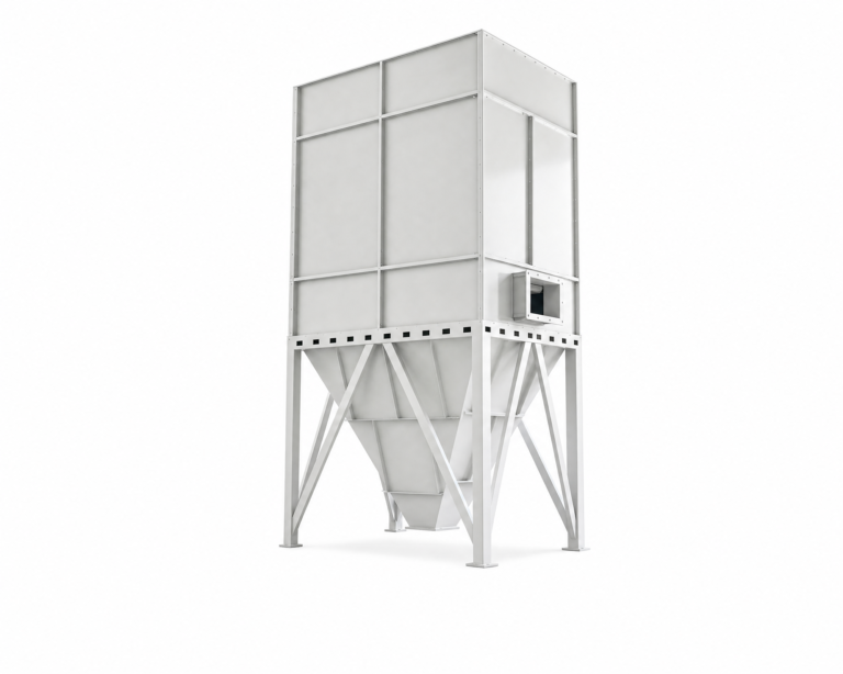
Картриджные пылесборники эффективно справляются с мелкой взвешенной в воздухе пылью при компактных габаритах, что делает их наиболее распространенным выбором в качестве первичного пылесборника для операций шлифования и резки с низкой и средней интенсивностью. Импульсно-струйные рукавные пылесборники подходят для процессов с большими объемами и непрерывной загрузкой, где допустимы более крупные габариты и более высокая первоначальная стоимость. Циклонные сепараторы не являются устройствами конечной фильтрации; их роль заключается в удалении более тяжёлых и крупных частиц и снижении нагрузки на последующий фильтр, что продлевает срок его службы и со временем уменьшает перепад давления. Сочетание циклона с картриджным фильтром для процессов шлифования с высокой пыленагрузкой — это многоступенчатое решение, позволяющее избежать преждевременного забивания фильтра, что является одной из наиболее распространённых причин внеплановых остановок на техническое обслуживание на предприятиях по обработке металлов.
| Тип коллектора | Лучшее для | Типичная стадия системы | Основное ограничение |
|---|---|---|---|
| Картриджный пылесборник | Мелкая воздушная пыль, компактная конструкция, основная фильтрация при слабой и средней нагрузке. | Основной пылеуловитель. | Не предназначено для переработки больших объемов сыпучих материалов без предварительного сепаратора; выбор системы улавливания горючей пыли должен основываться на степени опасности материала, а не только на расходе воздуха. |
| Рукавный (импульсно-струйный) пылесборник | Более крупные системы, более высокая интенсивность воздушного потока, постоянная высокая запыленность. | Основной пылеуловитель для систем с высокой производительностью. | Большая занимаемая площадь и более высокая первоначальная стоимость; при этом для применения с горючими материалами по-прежнему требуется анализ риска запыленности. |
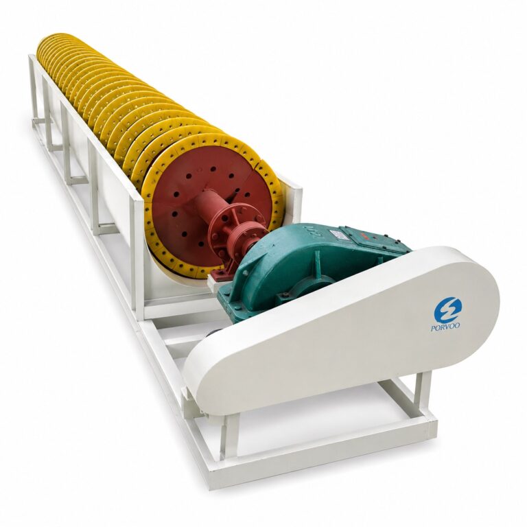
| Циклонный сепаратор | Более тяжелые частицы, высокая запыленность, предотвращение образования искр. | Предварительный сепаратор перед окончательной фильтрацией. | Сам по себе он неэффективен для улавливания мелкой взвешенной в воздухе пыли; для соблюдения предельных значений выбросов его необходимо использовать в сочетании с картриджным или рукавным пылесборником. |
Решение о мобильности представляет собой отдельный аспект, который часто путают с выбором типа коллектора, однако оно основывается на иных критериях.
| Фактор | Когда целесообразно использовать Mobile Collector | Когда целесообразно использовать стационарный коллектор |
|---|---|---|
| Местоположение источника пыли | Источник часто меняется, либо прокладка стационарных воздуховодов нецелесообразна. | Источник фиксированный и может быть подключен к воздуховоду на постоянной основе. |
| Время выполнения процесса | Периодическое использование или эпизодическое перемещение между рабочими местами. | Процесс протекает непрерывно и требует специальной системы отвода. |
| Потребность в воздушном потоке | Системы с низким расходом воздуха, где достаточно небольшого портативного устройства. | Высокие требования к расходу воздуха, обусловливающие необходимость установки более крупного стационарного коллектора. |
Переносной агрегат, который на момент покупки кажется универсальным, оказывается недостаточным, когда технологические требования к расходу воздуха превышают возможности мобильного пылесборника или когда непрерывная эксплуатация требует более длительного рабочего цикла, чем предусмотрено в технических характеристиках агрегата. Обратная проблема — установка стационарного пылесборника без предварительного согласования трассы воздуховодов — создает ограничения по доступу и техническому обслуживанию, которые усугубляются на протяжении всего срока службы системы. Для стационарных шлифовальных рабочих мест с постоянно высокими требованиями к расходу воздуха Картриджный пылесборник и Импульсный струйный пылеуловитель представляют различные варианты мощности и конфигурации в рамках одного семейства коллекторов.
В случае применения в условиях горючей пыли необходимо особое внимание уделить одному моменту: ни один выбор пылесборника — независимо от номинального расхода воздуха или эффективности фильтра — не гарантирует соответствие объекта требованиям, предъявляемым к горючей пыли. Выбор пылесборника для горючей пыли должен основываться на анализе опасности пыли конкретного материала, включающем оценку воспламеняемости, индекс дефлаграции и классификацию зоны. Выбор, основанный исключительно на показателях CFM или мощности в лошадиных силах, является задокументированной причиной неудач. Пылесборник поддерживает стратегию контроля опасности с учетом требований нормативных документов; он не заменяет программы поддержания чистоты, меры контроля источников возгорания или сам анализ опасности.
Укажите параметры статического давления среды в кубических футах в минуту (CFM) и условия доступа для технического обслуживания
CFM — это расчетный показатель производительности, а не каталожный номер. Необходимый расход воздуха на коллекторе зависит от конкретного сочетания типа источника, геометрии вытяжного колпака, расстояния улавливания, трассы воздуховода, поведения частиц и количества одновременно работающих точек улавливания. Использование приблизительного значения CFM без предварительного учета этих факторов приводит либо к созданию системы недостаточной мощности, которая не способна улавливать загрязнения, либо к созданию системы избыточной мощности, которая тратит энергию впустую и нарушает рабочую обстановку — особенно в конфигурациях с вытяжными камерами, где слишком большой расход воздуха может так же мешать процессу, как и слишком маленький.
| Фактор | Влияние на требуемый расход воздуха (CFM) | Что необходимо уточнить |
|---|---|---|
| Источник пыли и технологический процесс | Различные технологические процессы выделяют пыль с разной интенсивностью и с различными характеристиками пылевого шлейфа, что обусловливает необходимость изменения скорости улавливания. | Тип инструмента, скорость работы, материал, а также то, является ли пыль лёгкой и воздушной или тяжёлой и быстро распространяющейся. |
| Конструкция козырька и расстояние съемки | Форма и размер вытяжного колпака, а также расстояние до источника загрязнения напрямую определяют расход воздуха, необходимый для обеспечения требуемой скорости улавливания. | Тип кожуха (щелевой, круглый, закрытый), размеры щелей и максимальное практическое расстояние от источника во время работы. |
| Воздуховоды | Длина, диаметр и фитинги воздуховодов создают статическое давление, которое вентилятор должен преодолеть; воздуховоды недостаточного сечения увеличивают сопротивление. | Схема прокладки воздуховодов, количество колен, места отвода ответвлений и доступное пространство для прокладки воздуховодов. |
| Поведение частиц | Более тяжёлые или крупные частицы требуют более высокой скорости перемещения, чтобы оставаться в воздухе в воздуховоде; мелкую лёгкую пыль можно улавливать при более низких скоростях. | Диапазон размеров частиц, плотность, а также то, является ли пыль сухой или влажной. |
| Количество пунктов сбора | Общий расход в кубических футах в минуту (CFM) представляет собой сумму расходов всех точек отбора, которые должны работать одновременно, а не только расход самой крупной отдельной точки. | Сколько станций работает одновременно и будут ли использоваться заслонки для отсечения неиспользуемых ветвей. |
При выборе вентилятора необходимо учитывать общие потери статического давления в системе, а не только внутреннее сопротивление коллектора. Стационарные коллекторы обычно работают в диапазоне статического давления примерно от 15,7 до 39,7 дюймов водяного столба, который служит ориентиром при проектировании — фактические требования системы зависят от длины воздуховодов, количества фитингов и конфигурации отводов. Вентилятор, выбранный без анализа кривой системы, не обеспечит расчетный расход воздуха в установленной конфигурации, независимо от того, что указывают его номинальные характеристики на заводской табличке.
Выбор фильтрующего материала основывается на аналогичной логике: он должен соответствовать характеристикам пыли, определённым на этапе определения источника загрязнения, а не просто отражать стандартные предложения из каталога продукции.
| Тип фильтра | Характеристики подходящей пыли | Ключевое соображение |
|---|---|---|
| Картридж | Мелкая сухая пыль; умеренная нагрузка; широко применяется при шлифовании и резке металлов. | Большая площадь фильтрации при компактных габаритах; может быстро забиваться, если пыль липкая или маслянистая. |
| Звезда | Мелкая и среднезернистая пыль; альтернатива картриджу с гофрированным фильтрующим материалом в форме звезды. | Обладает большой площадью поверхности; эффективность зависит от номинальной производительности фильтрующего материала и возможности его очистки. |
| Сумка | Возможны более высокие нагрузки по пыли, больший размер частиц и применение в условиях высоких температур. | Более низкая эффективность фильтрации очень мелкой пыли, если не предусмотрена вторичная фильтрация; более габаритный корпус. |
| HEPA / Вторичный высокоэффективный фильтр | Очень мелкая или опасная пыль, в отношении которой должны соблюдаться строгие нормы качества воздуха в помещениях или предельные значения выбросов. | Рекомендации по применению фильтров HEPA не должны заменять полноценное проектирование системы; необходимо убедиться, что установленный выше по потоку коллектор сначала справляется с основной нагрузкой, чтобы защитить высокоэффективную ступень. |
Решение о выборе фильтров HEPA требует особого внимания. Фильтрация HEPA целесообразна в случаях, когда пыль очень мелкая, опасна или подпадает под строгие ограничения по качеству воздуха в помещении — однако выбор фильтров HEPA без обеспечения того, чтобы предшествующая система сначала справлялась с основной нагрузкой, приведет к быстрому забиванию высокоэффективных фильтрующих элементов, что повысит перепад давления и вызовет необходимость их преждевременной замены. Чрезмерный акцент на эффективности фильтра при одновременном игнорировании скорости улавливания у вытяжного колпака по-прежнему не обеспечивает защиту работников; этап фильтрации имеет значение только в том случае, если пыль до него вообще доходит.
Возможность доступа для технического обслуживания — это параметр проекта, который зачастую рассматривается как второстепенный аспект при закупке оборудования. Легкий доступ к фильтрам, вентиляторному узлу и месту выхода пыли напрямую определяет, будет ли на самом деле проводиться плановое техническое обслуживание. Установленные в стесненных или неудобных местах пылесборники приводят к накоплению отложенных работ по техническому обслуживанию; отложенное обслуживание фильтров увеличивает перепад давления в системе, снижает расход воздуха в точке улавливания и вновь создает те условия воздействия, для предотвращения которых и была установлена система. Требования к доступу следует согласовать с учетом монтажного пространства до заказа пылесборника, а не выявлять их во время первой замены фильтра.
При приемочной проверке убедитесь в правильном воздушном потоке и эффективности системы защиты от видимой пыли
Приемка системы пылеудаления должна основываться на наблюдаемых эксплуатационных показателях в реальных условиях работы, а не только на контрольных списках по монтажу. Практическим критерием является то, удается ли визуально убедиться в улавливании пыли на рабочем месте в ходе реального производственного процесса — при использовании стандартного инструмента, при обычном поведении оператора и при обычной производительности.
Короткое видео, снятое на рабочем месте во время выполнения процесса, служит убедительным доказательством адекватности системы улавливания. Оно демонстрирует поведение облака пыли, расстояние между точкой образования пыли и передней поверхностью вытяжного колпака в режиме реальной работы, а также показывает, выходит ли оператор за пределы зоны улавливания в процессе работы. Подобные наблюдения при приемочных испытаниях позволяют выявить недостатки, которые упускаются при статических измерениях — например, когда вытяжной колпак, правильно установленный для стационарной конфигурации, смещается во время работы из-за того, что естественное положение тела оператора приводит к изменению угла наклона обрабатываемой детали. Стандарт ISO 10780:1994 определяет рамки испытаний для измерения скорости и объемного расхода в контексте выбросов из стационарных источников; при приемочных испытаниях рабочего места измерения скорости у лицевой поверхности вытяжного колпака и в точках ответвления воздуховода позволяют подтвердить, достигается ли расчетный расход воздуха в установленной конфигурации.
Если измеренный расход воздуха не соответствует расчетному, важно соблюдать последовательность диагностики. Прежде чем делать вывод о том, что коллектор имеет недостаточный размер, проверьте давление в ответвлениях воздуховода; часто основной причиной является фитинг воздуховода, замененный во время монтажа, частично закрытый заслонка или длина ответвления, превышающая расчетную. Модернизация коллектора до устранения проблем в системе воздуховодов не решит проблему снижения производительности и усложнит будущее техническое обслуживание. Производительность системы улавливания, подтвержденная при приемке (с документальным подтверждением), также служит базовым показателем для мониторинга ухудшения характеристик с течением времени, поскольку любое заметное увеличение количества пыли на рабочих местах в ходе последующей эксплуатации указывает на изменения в системе, которые следует изучить: загрязнение фильтров, износ вентилятора или физические изменения в трассе воздуховодов.
Определите следующую страницу, исходя из самой слабой точки захвата
Следующее техническое задание или решение о закупке должно определяться тем элементом рабочего места, который в данный момент является наименее проработанным, а не тем оборудованием, которое наиболее бросается в глаза. Правильно спроектированный коллектор в сочетании с ненадлежащим образом сконструированной вытяжной шапкой — это система, которая не сможет обеспечить требуемую производительность. Правильная конфигурация вытяжной шапки, ограниченная коллектором недостаточной мощности, — это другой, но столь же предсказуемый случай неэффективности.
Что касается именно столов с нисходящим потоком, то Промышленный стол сухого/мокрого помола с пригрузом и Промышленный портативный пылесборник охватывают различные позиции в спектре мобильности и интеграции с рабочими станциями — и для того, чтобы выбрать между ними, сначала необходимо определить исходные параметры. Данные подробное руководство по столам для шлифования с нисходящим потоком воздуха более подробно рассматривает вопросы выбора систем с мокрой и сухой обработкой для обработки металла, камня и композитных материалов на этих рабочих местах; Полное руководство по портативным пылесборникам предназначено для мобильных приложений в тех случаях, когда использование стационарных воздуховодов нецелесообразно.
На данном этапе честный вопрос, который следует задать при аудите, прост: какой из точек отбора в схеме расположения рабочих мест характеризуется наибольшей неопределённостью — в скорости улавливания, геометрии вытяжного колпака, диапазоне движений оператора или сопротивлении тракта воздуховода? Именно этот вопрос необходимо решить до утверждения технических характеристик коллектора или оформления заказа на его закупку.
Эффективная система пылеудаления на рабочем месте — это, в конечном счете, вопрос правильной последовательности действий. Системы, которые не справляются с задачей на производстве, почти всегда пропускают этап определения источника загрязнения и сразу переходят к выбору оборудования, что приводит к несоответствию между возможностями пылесборника и фактическими требованиями геометрии вытяжного колпака в точке улавливания. Самое полезное, что может сделать специалист по техническим требованиям перед выдачей документа на закупку, — это убедиться, что тип материала, интенсивность запыленности за смену, расстояние улавливания, количество точек одновременного улавливания и трасса воздуховода задокументированы и внутренне согласованы, поскольку каждый из этих параметров влияет на требуемые номинальные характеристики пылесборника.
Перед принятием следующего решения по техническим характеристикам необходимо ответить на следующие конкретные вопросы: утвержден ли окончательный проект вытяжного колпака и подтверждена ли скорость улавливания при фактическом рабочем расстоянии? Составлена ли схема системы воздуховодов с достаточной степенью детализации для расчета общей статической потери давления? И для каждого рассматриваемого типа пылесборника — будь то картриджный, импульсно-струйный или переносной — учитывает ли выбор ступенчатость засыпания пылью, доступ для технического обслуживания в месте установки и специфические характеристики пыли, образующейся в данном технологическом процессе? Ответы на эти вопросы позволяют быстро сузить круг выбора пылесборников и предотвратить возникновение самой дорогостоящей категории проблем после установки: системы, которая была правильно рассчитана на бумаге, но так и не была адекватно адаптирована к рабочему месту, для обслуживания которого она предназначалась.
Часто задаваемые вопросы
Вопрос: Что следует делать, если источник пыли на рабочем месте меняет своё расположение или оператор активно перемещается в ходе рабочего процесса?
A: Стационарный вытяжной колпак или неподвижный коллектор, скорее всего, не являются подходящей исходной конфигурацией. Когда точка образования пыли смещается вследствие перемещения оператора или изменения положения заготовки, более практичным решением, чем стационарный вытяжной колпак со щелями, станет пылезащитная камера или гибкий вытяжной манипулятор, установленный на переносном агрегате. Решение зависит от того, можно ли обеспечить свободу движений оператора внутри камеры без ухудшения доступа к детали: если да, то камера ограничивает объём загрязнённого воздуха, подлежащего очистке; если нет, то переносной пылесборник со шарнирным рукавом более надёжно отслеживает источник загрязнения, чем любое фиксированное соединение с воздуховодом.
Вопрос: В каких случаях установка циклонного предварительного сепаратора действительно оправдана с экономической точки зрения по сравнению с простой модернизацией основного коллектора?
A: Использование циклонного предсепаратора оправдывает себя в тех случаях, когда основная часть пылевой нагрузки состоит из более крупных и тяжелых частиц, с которыми в противном случае пришлось бы непосредственно справляться картриджному или мешочному фильтру. При высокопроизводительном измельчении или резке, в ходе которых образуется смешанный по размеру поток частиц, циклон позволяет экономично удалять крупную фракцию, продлевая срок службы фильтра и снижая рост перепада давления между циклами очистки. Увеличение размера первичного коллектора само по себе не решает проблему преждевременного забивания фильтра, если скорость загрузки превышает способность механизма очистки; многоступенчатая система решает проблему загрузки у источника, тогда как увеличение размера лишь добавляет производительность, которую фильтр всё равно может исчерпать преждевременно.
Вопрос: Существует ли пороговое значение загрузки пылью или объема смены, при превышении которого следует отказаться от использования картриджного пылесборника в пользу импульсно-струйного рукавного фильтра?
A: Единого опубликованного порогового значения не существует, однако на практике переходный момент наступает, когда постоянная высокая запыленность превышает возможности цикла очистки картриджа — об этом свидетельствует более быстрый рост перепада давления между импульсами очистки, чем предусмотрено в расчетах системы. Для операций шлифования с низкой или умеренной интенсивностью, при которых образуется мелкая взвешенная в воздухе пыль в управляемых объемах за смену, в качестве основного оборудования обычно подходит картриджный пылесборник. Когда технологический процесс работает непрерывно с высокой производительностью, генерирует абразивные частицы, ускоряющие износ фильтрующих элементов, или требует большей установки по площади, импульсно-струйный рукавный фильтр становится более надежным выбором в долгосрочной перспективе. Решающим фактором является объем пыли за смену, зафиксированный на этапе определения источника загрязнения, а не только номинальная производительность по воздушному потоку.
Вопрос: Можно ли использовать видеотест при приеме-сдаче и измерение скорости воздушного потока в вытяжном колпаке в качестве метода постоянного мониторинга или только при первоначальном вводе в эксплуатацию?
A: Оба метода напрямую применимы к текущему мониторингу производительности, а не только к вводу в эксплуатацию. Видеозапись исходного состояния и измерение скорости воздушного потока на лицевой поверхности вытяжного колпака, выполненные при приемочных испытаниях, создают эталонные условия, с которыми можно сравнивать последующую эксплуатацию. Любое заметное увеличение количества пыли на рабочем месте во время производства — по сравнению с принятым базовым уровнем — является ранним индикатором изменения в работе системы, которое стоит изучить: загрязнение фильтра, приводящее к увеличению перепада давления; износ вентилятора, снижающий подаваемый воздушный поток; или физическое изменение трассы воздуховода, уменьшающее скорость воздушного потока в отводах. Повторные измерения, проводимые через запланированные интервалы технического обслуживания или при каждом изменении условий технологического процесса, позволяют выявить ухудшение рабочих характеристик до того, как оно приведет к воздействию вредных факторов на работников или к серьезному сбою системы.
Вопрос: Если анализ опасности, связанной с горючими пылями, ещё не завершён, следует ли приостановить закупку пылесборников до его завершения?
A: Да, с закупкой следует подождать. Выбор пылесборника для условий с горючими пылями без завершённого анализа опасности, связанной с пылью, означает, что конфигурация взрывозащиты, классификация зоны и требования к контролю воспламенения остаются неопределёнными — а именно эти требования напрямую определяют, какая конструкция пылесборника является допустимой, а не просто предпочтительной. Заказ оборудования до завершения анализа опасности сопряжён с риском выбора пылесборника, который после завершения анализа придётся заменить или существенно модифицировать. Анализ опасности является исходным условием, определяющим выбор оборудования; нарушение этой последовательности является одной из задокументированных причин несоблюдения требований по взрывобезопасности при работе с горючими пылями.