Sizing a buffer tank for a batch filter press starts from one fact: the press accepts slurry only during its filling and filtration steps, and accepts nothing while plates open, cake discharges, cloths wash or the machine sits idle for planned maintenance. The tank must therefore hold the slurry that arrives during every non-receiving period, not just the slack between feed pumps. The quantity that sets the size is the largest cumulative difference between what arrives and what the press withdraws, traced across one complete cycle including any planned downtime, with the usable volume of the tank — the part actually available between the working levels and above the draw-off — separated from its nominal capacity.
Map continuous inflow against the complete batch cycle
Build a time-based profile of inflow and press withdrawal across the whole cycle before any volume is calculated. The cycle has a receiving phase and a non-receiving phase, and the non-receiving phase is usually the longer half of the sizing problem once opening, discharge, cloth cleaning and planned stoppages are added together. Multiplying average plant flow by filtration time answers a different question than the one the tank has to answer.
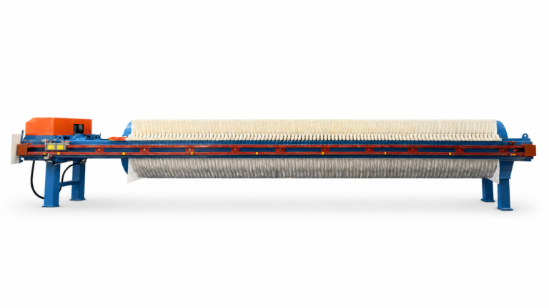
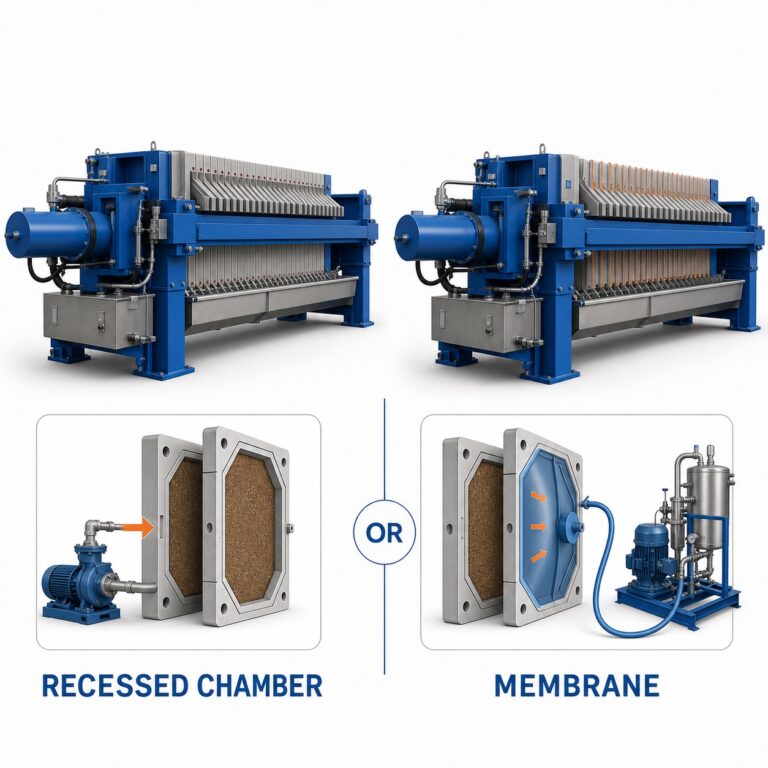
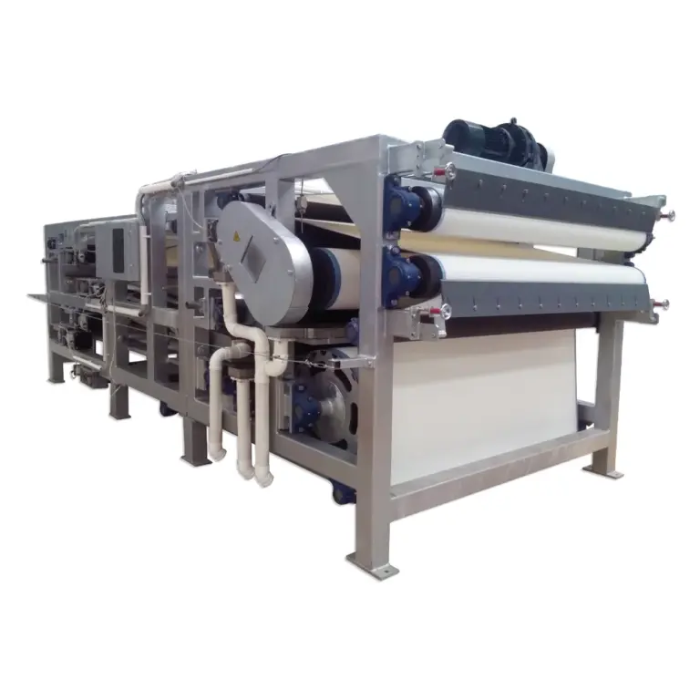
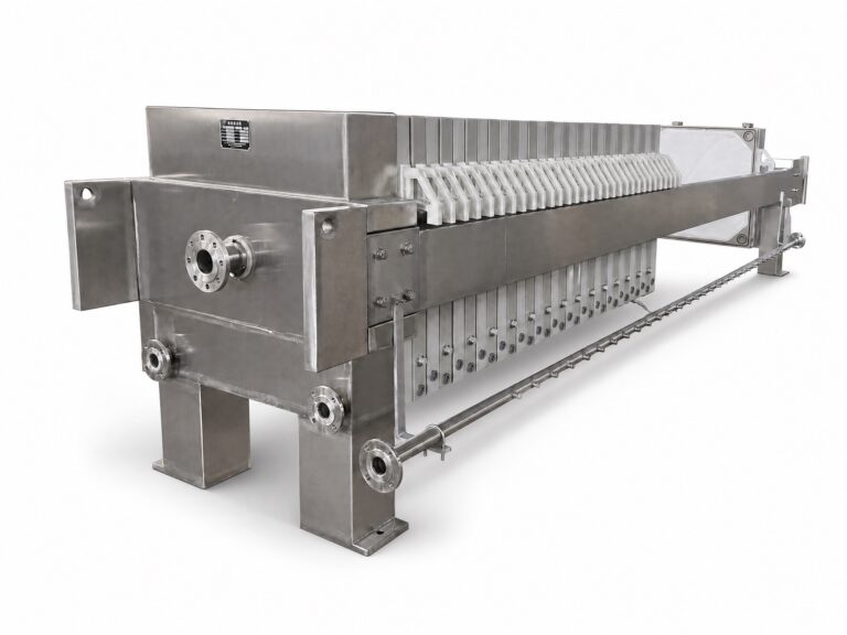
The reason is mechanical. A recessed-plate press closes, fills and filters as a batch; the Информационный бюллетень Агентства по охране окружающей среды США (EPA) о биологических осадках, посвященный фильтр-прессам с утопленными пластинами describes that batch sequence, in which the feed pump charges the chambers, filtrate leaves through the cloths, and the plates then open for cake discharge before the next charge begins. During the opening and discharge steps the feed line is shut, so incoming slurry has nowhere to go but the tank. That fact sheet addresses US municipal biosolids, so its mechanics of feeding, filtrate removal and discharge are the transferable part; its cycle times and performance figures do not carry across to ceramic, stone or mineral slurry.
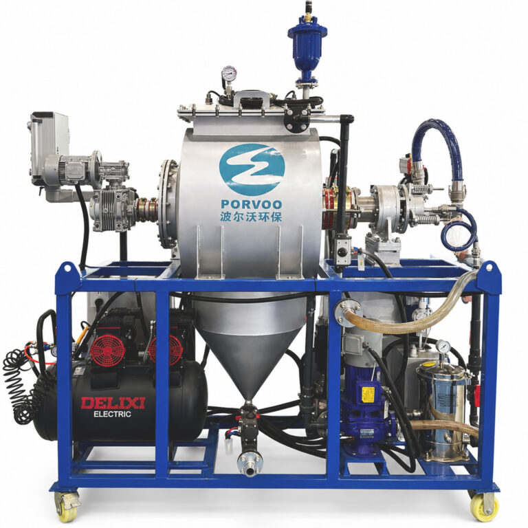
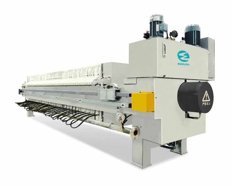
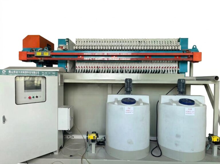
Begin the profile from the press configuration that will actually be installed, because an automatic press with mechanized plate shifting and cloth washing has a different non-receiving window than a manually shifted machine. On a PORVOO fully automatic filter press, the controlled sequence fixes when the feed valve is open, and that schedule, not an averaged throughput figure, is what the buffer calculation needs.
One condition genuinely reduces the volume assigned to this tank: another receiving route that is verified as available during the same interval, such as a second press taking part of the stream or a thickener with real spare capacity. If such a route exists, assign its share explicitly in the profile. If it does not, the tank carries the whole non-receiving period.
Calculate the accumulation swing and usable tank volume
The buffer volume follows from a running balance: for each interval, add the incoming volume, subtract the press withdrawal, and carry the result forward. The largest value this cumulative balance reaches over the cycle is the required accumulation swing — the process quantity the tank must be able to take up and then give back when the press resumes feeding.
That swing is not the tank size. The geometrical capacity of a vessel and the volume a process can actually use are different quantities, and several things sit between them. Volume below the draw-off connection cannot be withdrawn. A settled solids bed occupies space that the slurry cannot reclaim without resuspension. The working range between low and high operating levels is narrower than the shell. Each of these subtracts from what the swing can occupy, so the sizing sequence is: establish the swing first, then add the unusable volume, the operating level allowances and any project-defined contingency as separate, named quantities rather than folding them into a single safety factor.
Reserve volume, freeboard and high-level protection belong to the actual vessel design and the site’s process and protective requirements; the swing calculation tells the designer how much working volume those allowances have to surround. Keeping the two separate also makes the sizing auditable later — if the cycle changes, the swing recalculates without disturbing the mechanical allowances.
Build a time-based buffer worksheet
| Worksheet entry | Что записывать | Effect on the buffer calculation |
|---|---|---|
| Time interval | The interval used for each inflow and withdrawal entry | Keeps incoming volume and press draw on the same time basis. |
| Operating state | Filling, filtration, opening, discharge, cleaning or planned downtime | Shows which part of the complete batch cycle each balance entry represents. |
| Incoming volume | Slurry arriving during the interval | Adds to the volume that must be received. |
| Press draw | Actual press withdrawal during the interval; use zero during discharge unless the offered arrangement supports otherwise | Subtracts the volume taken by the press and exposes periods when it accepts no slurry. |
| Cumulative balance | Running incoming volume minus press withdrawal | Reveals the largest required accumulation swing. |
| Available receiving route | Any verified alternative route available during the interval | Establishes whether some incoming volume can be assigned outside this tank. |
A worksheet turns the cycle into numbers by recording, interval by interval, what arrived, what the press took and where the balance stood. Its value is that it exposes the batch gap directly instead of hiding it inside an average flow rate, and it lets the engineer re-run the sizing against a longer discharge step, an added cloth wash or an unplanned outage by changing one column rather than rebuilding the assumption.
Two entries carry most of the decision weight. The press draw column should show zero during the discharge step unless the offered arrangement specifically supports feeding at that moment, because assuming continuous withdrawal is the single error that most often undersizes a buffer. The operating-state column keeps each balance line tied to a real machine condition, so a reviewer can see which phase produced the peak rather than inferring it from the numbers.
Where two or more presses share the stream, the worksheet needs their actual overlapping withdrawal schedules. Duplicating one press’s profile and doubling the draw assumes a staggered sequence that may not exist; if both machines discharge within the same window, the buffer sees a combined non-receiving period, not two offset ones. The control philosophy that governs cycle staggering is the fact that settles this, and it comes from the press supplier’s sequence description.
Keep stored slurry suitable for press feeding
A tank that holds enough volume can still send the press material it cannot filter consistently. Ceramic, stone and mineral slurries settle according to particle size and density difference, so stored slurry stratifies unless agitation keeps it suspended, and the press then receives a varying solids concentration from one charge to the next — which changes fill time, cake thickness and discharge behavior.
Metso’s OKTOP feed tank leaflet links buffering directly with homogeneous feed and settlement prevention, connecting tank form, agitator placement, usable volume, operating levels and outlet position as one arrangement rather than independent choices. The practical reading is that suspension performance and usable volume are coupled: an agitator sized for a full tank may not maintain suspension at low level, and the outlet position decides whether the last working volume is slurry or a solids bed. Those relationships are specific to that feed-tank family and its geometry, so they describe what to evaluate, not dimensions, speeds or power for another project’s tank.
Evaluate suspension, residence time, usable levels and draw-off position together using representative slurry from the actual process stream and the agitation arrangement being proposed. Residence time matters on its own terms: slurry that sits through a long planned downtime can thicken or compact in ways that a short-cycle sample never shows. Where a plant recycles process water, the concentration arriving at the tank also shifts with the loop, so the sample should reflect the recycled condition rather than fresh make-up.
Match the outlet and pump to batch withdrawal
The feed pump duty comes from the batch withdrawal rate, not from the average plant inflow. A press that fills in a fraction of its cycle draws at a rate well above the arrival rate, and sizing the pump on average flow leaves fill time stretched and the cycle lengthened — which in turn enlarges the non-receiving window and the buffer the tank must provide. Pump duty and buffer size are coupled through the cycle.
Solids behavior sets the rest of the selection. KSB’s centrifugal pump reference on solids transport relates particle size, density difference, concentration and velocity to transport behavior, with concentration-dependent losses and the risk of settling, clogging and wear. Applied to a buffer outlet, that means the withdrawal velocity has to stay high enough to keep solids moving through the suction line, while the outlet position has to stay clear of any settled bed; a low-level draw that works at design concentration can pull compacted solids when the tank is pumped down after a long hold. Suction conditions change with level too, so the low operating level and the pump’s net positive suction head requirement have to be checked as one condition.
Assess the solids behavior, operating level range, pipe run and required batch duty together rather than in sequence. Pump curves and testing on representative slurry are what resolve the actual transport and suction limits for a given route; the KSB reference supplies the general relationships, not a transport velocity or material selection for this installation.
Define the response when the press remains unavailable
A buffer tank postpones an imbalance; it cannot absorb an indefinite one. If the press or the cake receiver stays unavailable beyond the sized swing, continuity depends on a defined plant response, so that response should be agreed before anyone adds a nominal emergency allowance to the tank volume. Extra volume without an agreed action simply moves the overflow further into the future.
Three things need to be settled. First, what happens at high level — which alarm, which interlock and which authorized destination receives slurry, defined by the site’s process, environmental and protective design. Second, how the incoming process is coordinated, since reducing or stopping the upstream operation is often the only response that actually closes the balance. Third, which alternative destination is authorized, because any overflow, diversion or temporary storage route has to meet the site’s discharge and waste-handling requirements before it can be used. In ceramic recycling loops in particular, the cake and filtrate destinations beyond the tank set what a diversion is permitted to touch. Decisions to divert, hold or return the line to service are made under the project’s approved procedure by its designated approver, not by the buffer calculation.
For a useful discussion with a press supplier about this part of the design, come with the inflow rate and how it varies, the slurry’s solids concentration and settling behavior, the full cycle breakdown including planned cleaning and downtime, the working level range and draw-off position of the proposed tank, and any verified alternative receiving route. With those in hand, the swing, the pump duty and the high-level response can be resolved together rather than one at a time.
Часто задаваемые вопросы
Q: Can an existing slurry tank be reused as the buffer?
A: It may be suitable if its usable operating volume covers the calculated accumulation swing and the slurry remains suitable for feeding. Check the actual operating levels, settled-solids allowance and draw-off position before comparing capacity. Nominal tank volume alone does not establish suitability; the outlet and pump must also accommodate the required batch withdrawal.
Q: Would adding a second filter press remove the need for a buffer?
A: Not automatically. Use the two presses’ actual withdrawal schedules together to check whether incoming slurry can still accumulate. Staggered operation must be assessed across the complete cycles, including cleaning and downtime; do not assume that a second press always provides an available receiving route.
Q: If filtration becomes faster, can the buffer tank be made proportionally smaller?
A: A shorter filtration period does not establish a proportional reduction in buffer demand. Recalculate the cumulative balance using the revised withdrawal schedule and the other cycle periods, including opening, discharge and cleaning. The useful reduction is the change in the largest required accumulation swing, with operating allowances considered separately.
Q: Will a larger buffer tank cure inconsistent slurry feed to the press?
A: More capacity alone does not establish consistent feed. If slurry settles or changes consistency during storage, assess residence time, suspension, operating levels and draw-off position with representative slurry and the proposed agitation arrangement. A tank can have enough volume while retaining a solids bed or delivering inconsistent material.
Q: Can the upstream process keep running throughout an extended press outage?
A: Only while a verified receiving route and sufficient available capacity remain. Compare the expected incoming volume during the outage with the tank’s available operating volume, then define the high-level response and upstream coordination. A finite buffer cannot support an indefinite outage; any alternative destination needs to be authorized for the site.