Dimensionar um tanque de sedimentação com base na vazão média diária é uma das formas mais confiáveis de ser aprovado na revisão do projeto e, mesmo assim, falhar na fase de comissionamento. As linhas de produção de cerâmica e pedra geram pulsos curtos e intensos de sólidos durante os ciclos de limpeza em lote e nos períodos de pico de corte, o que pode comprometer o desempenho de sedimentação mais rapidamente do que um tanque fixo consegue se recuperar — e, quando isso acontece, o problema raramente se manifesta como um transbordamento óbvio. Ele se manifesta como um aumento gradual na turbidez da água reciclada, que só se torna mensurável durante a validação ou na primeira auditoria ambiental; nesse momento, a geometria do tanque, o sistema de dosagem e o cronograma de retirada de lodo já estão definidos. A decisão que resolve isso é simples de enunciar, mas difícil de executar: definir a meta de água reutilizada antes de alterar qualquer dimensão do tanque e, em seguida, dimensionar todos os parâmetros com base no pior turno operacional, e não na média.
Qual meta de reciclagem de água deve ser definida inicialmente no projeto do tanque?
A meta de reutilização não é um resultado posterior ao dimensionamento do tanque — é a restrição que dá sentido ao dimensionamento do tanque. Uma fábrica que estabelece um limite máximo de sólidos em suspensão para a água reciclada, por exemplo, para circuitos de resfriamento, água de pressão ou circuitos de corte úmido, possui um limite de qualidade fixo ao qual todas as variáveis do processo a montante devem se adequar. Sem essa referência, o tempo de retenção torna-se uma estimativa e a dosagem passa a ser reativa.
O ponto de partida prático é traduzir a meta de reutilização em um requisito mínimo de desempenho de sedimentação e, em seguida, trabalhar retroativamente até o tempo de retenção hidráulica que o tanque deve manter em condições de vazão de pico. Um tempo de retenção hidráulica de 90 minutos sob vazão instantânea de pico é um limite de dimensionamento amplamente utilizado que garante que o tanque possa reter os sólidos que chegam por tempo suficiente para que as partículas se sedimentem antes que a água clarificada alcance a zona de saída. Para estações que operam em modo de lote, em vez de fluxo contínuo — ciclos de produção intermitentes, descarga periódica —, um período mínimo de sedimentação em repouso de 60 minutos, sem adição ou descarga, oferece a garantia equivalente de sedimentação durante cada ciclo de lote. Esses valores funcionam como referências de projeto, não como mínimos regulatórios universais, e sua utilidade depende inteiramente de se os fluxos e as entradas de sólidos utilizados para calculá-los refletem condições de pico reais, em vez de dados médios.
A norma ISO 46001:2019 define a gestão da eficiência hídrica como um sistema que exige metas de desempenho definidas antes da seleção de intervenções técnicas. Esse princípio se aplica diretamente neste caso: uma estação que não definiu sua meta de qualidade da água reciclada não tem base para selecionar o tempo de retenção, a configuração dos tanques, a dosagem de produtos químicos ou a frequência de retirada de lodo. A sequência é importante. Primeiro, a meta de reutilização; depois, a caracterização dos sólidos recebidos; e, por fim, o dimensionamento do tanque — inverter essa ordem resulta em um tanque que pode atender aos critérios de carga superficial, mas que, de forma consistente, não atinge a qualidade da água que o processo a jusante realmente exige.
Como o tempo de retenção interage com os picos de sólidos provenientes da produção
O tempo de retenção não é um buffer estático — ele se comporta de maneira diferente dependendo se a carga de sólidos é constante ou flutuante, e as fábricas de cerâmica e pedra quase sempre apresentam cargas flutuantes. As operações de trituração, polimento e corte com serra geram continuamente uma quantidade baixa a moderada de sólidos em suspensão; no entanto, a limpeza em lotes dos equipamentos de corte, a lavagem periódica de partículas finas acumuladas ou as purgações realizadas nas trocas de turno podem causar picos acentuados e breves na concentração de sólidos na entrada. Esse pico altera o comportamento de sedimentação mais rapidamente do que um tempo de retenção fixo é capaz de compensar.
O risco de falha em questão é mais acentuado em configurações compactas de decantadores com placas inclinadas e tubos. Esses projetos alcançam sua eficiência multiplicando a superfície efetiva de decantação em uma área ocupada reduzida, o que funciona bem sob cargas em estado estacionário. Sob cargas de choque, no entanto, sua menor tolerância a aumentos repentinos na concentração de sólidos em suspensão significa que as partículas podem sobrecarregar os canais entre as placas antes que o sistema de dosagem tenha tempo de responder com um aumento na dosagem de coagulante. O resultado é o arrastamento de partículas para a zona de clarificação, situação da qual é difícil se recuperar rapidamente, pois a geometria que torna o decantador compacto também limita o volume disponível para absorver e redecantar as partículas finas ressuspensas.
Os tanques de fluxo horizontal absorvem picos de sólidos de maneira mais estável. Seu volume maior e seu percurso de fluxo mais longo proporcionam o tempo de amortecimento necessário para que a sedimentação acompanhe um aumento repentino da carga, o que os torna mais tolerantes à variabilidade de produção característica das linhas de cerâmica e pedra. No entanto, há uma contrapartida: as configurações de fluxo horizontal apresentam descarga descontínua de lodo e distribuição irregular do fluxo ao longo da largura do tanque, o que significa que o gerenciamento do acúmulo de lodo exige um planejamento mais cuidadoso. Nenhum dos dois projetos elimina o problema dos picos de sólidos — eles apenas transferem esse risco de uma forma para outra, e a escolha certa depende de qual risco a unidade está mais bem equipada para gerenciar.
Quando a dosagem, a sedimentação e a remoção de lodo devem ser equilibradas entre si
Um tanque de sedimentação não é um dispositivo de zona única. Ele funciona por meio de cinco zonas que interagem entre si: entrada, sedimentação, armazenamento de lodo, zona tampão e saída. A zona tampão é a menos discutida, mas, sem dúvida, a mais crítica para a qualidade da água reciclada — ela fica entre a zona de acumulação de lodo e a zona de saída, e sua função é reter as partículas finas que escaparam da zona de sedimentação e promover sua ressedimentação por meio da colisão entre as partículas antes que elas cheguem à saída da água clarificada. Quando o momento da remoção do lodo é mal gerenciado, a zona de lodo se expande para dentro da zona tampão, eliminando essa margem de ressedimentação e permitindo que as partículas finas cheguem até a saída.
A dosagem e a sedimentação são interdependentes de uma forma que se torna evidente quando se considera o que acontece às partículas que ficam abaixo da velocidade do fluxo ascendente em um tanque de fluxo contínuo. Em operação contínua, a velocidade ascendente criada pelo transbordamento do vertedouro arrasta qualquer partícula cuja velocidade de sedimentação seja baixa demais para superá-la. Isso significa que a dosagem de coagulante não se resume apenas à agregação de partículas — ela deve produzir flocos grandes e densos o suficiente para que a velocidade de sedimentação das partículas resultantes exceda, de forma confiável, as condições de fluxo ascendente dentro daquela geometria específica do tanque e daquela vazão. Se a dosagem for calibrada para o tamanho médio das partículas, em vez do tamanho das partículas no pior cenário, a fração fina proveniente de um pico de altos teores de sólidos passará para a zona de saída durante o período em que a coagulação ainda estiver se recuperando.
A consequência prática é que a taxa de dosagem, a frequência de retirada de lodo e o tempo de retenção no tanque não podem ser otimizados de forma independente. Um tanque dimensionado corretamente, mas com dosagem insuficiente de coagulante, deixará passar partículas finas. Um tanque com dosagem correta, mas com remoção de lodo pouco frequente, perderá progressivamente o volume da zona tampão e, eventualmente, prejudicará a clarificação, mesmo com tempos de retenção adequados. Estações que enfrentam problemas persistentes de qualidade da água reciclada, apesar do dimensionamento adequado dos tanques, frequentemente encontram a causa raiz em uma dessas falhas de integração, e não na própria geometria do tanque. Um Sistema inteligente de dosagem de produtos químicos Um sistema que ajuste a dosagem de PAM e PAC em resposta à carga de sólidos em tempo real pode diminuir a discrepância entre a resposta da coagulação e a variabilidade da carga — mas somente se a disciplina na retirada de lodo acompanhar essa evolução.
Por que as fábricas de cerâmica e pedra precisam dimensionar com base no pior turno e não com base no fluxo médio
O erro de planejamento de maior impacto neste setor é utilizar a vazão média diária para dimensionar o tanque. A produção de azulejos cerâmicos, o corte de pedras e a fabricação de louças sanitárias cerâmicas envolvem descargas periódicas com alto teor de sólidos que pouco se assemelham a uma média diária suavizada. Uma operação de limpeza em lote ou um período de pico de corte pode gerar um vazão e uma carga de sólidos que representam várias vezes a média horária, e essas são precisamente as condições nas quais o desempenho de sedimentação deve se manter para que a meta de água reciclada seja atingida de forma consistente.
Os três parâmetros de dimensionamento na tabela abaixo refletem isso: cada um deles é calculado com base nos valores de pico ou nos piores cenários, e não em médias.
| Parâmetro de dimensionamento | Limite de projeto | Implicações para o planejamento do pior turno |
|---|---|---|
| Taxa máxima de transbordamento (retangular) | 1,0 gpm/pé² (vazão máxima instantânea) | Evite falhas por transbordamento; dimensione o tanque para o vazão de pico, e não para a média |
| Acúmulo máximo de sedimentos | 25% de capacidade do tanque (média de três seções) | Planeje-se para a carga máxima de sólidos, a fim de evitar exceder o limite de armazenamento |
| Carga superficial nominal (secundária) | 450–600 gpd/pé² | Adicione um tanque de reserva quando o transbordamento de pico exceder a carga de projeto |
A taxa máxima de transbordamento de 1,0 gpm/pé² para tanques retangulares é particularmente esclarecedora, pois está explicitamente vinculada ao vazio instantâneo de pico, e não ao vazio médio diário. Um tanque dimensionado para o fluxo médio excederá esse limite durante os períodos de pico de produção, permitindo que partículas que, em condições normais, teriam se sedimentado, sejam transportadas para além do vertedouro de saída. O limite de acúmulo de sedimentos de 25% exige, da mesma forma, um planejamento para o pior cenário: uma estação com turnos ocasionais de alto teor de sólidos encherá seu reservatório de lodo mais rapidamente do que os cálculos de carga média prevêem e, uma vez que o sedimento se acumule além de 25% da capacidade do tanque, o volume efetivo de sedimentação fica comprometido. A faixa de carga superficial nominal de 450–600 gpd/ft² para tanques de sedimentação secundária reconhece implicitamente essa variabilidade ao exigir um tanque de reserva quando a taxa de transbordamento de pico projetada é excedida — um buffer de capacidade que o dimensionamento com base no fluxo médio, por definição, não pode levar em conta.
As orientações do Capítulo 11 do documento AP-42 da EPA sobre a fabricação de produtos cerâmicos fornecem um contexto útil para compreender as cargas de processo geradas pelas fábricas de cerâmica, embora não funcionem como uma norma de dimensionamento para o projeto de tanques de sedimentação. Seu valor, neste contexto, reside em reforçar o que os registros de produção frequentemente confirmam: a fabricação de cerâmica gera cargas de partículas que são episódicas e intensas, e não contínuas e constantes.
Como comparar layouts de retenção compactos com os de retenção longa
A ocupação de área e o desempenho do tratamento apresentam tendências opostas na escolha entre configurações compactas de placas inclinadas ou decantadores tubulares e tanques tradicionais de fluxo horizontal com retenção prolongada. Nenhum dos dois layouts é universalmente superior; a questão relevante é qual perfil de risco a estação pode gerenciar de forma mais confiável, considerando seu padrão de produção, os operadores disponíveis e a capacidade do sistema de dosagem.
| Aspecto do layout | Compactos (sedimentadores de placas/tubos) | Retenção prolongada (tanques tradicionais) |
|---|---|---|
| Pegada ecológica | Menor; aproveita o espaço vertical para reduzir a área | É necessário um espaço amplo |
| Manutenção e risco de entupimento | Sujeito a entupimentos; as placas/tubos precisam ser substituídos periodicamente | Não especificado |
| Desempenho com alto teor de sólidos | Sujeito a entupimentos em condições de alto teor de sólidos | Baixa eficiência do tratamento com sólidos em alta concentração |
| Restrição de projeto | Não especificado | Tanques retangulares exigem uma relação mínima entre comprimento (L) e largura (W) de 4:1 |
O risco de entupimento em projetos compactos não é uma preocupação meramente teórica para usinas de cerâmica e pedra — é o modo de falha operacional mais provável. As placas inclinadas e os tubos funcionam prolongando o percurso efetivo de sedimentação em um espaço vertical e horizontal reduzido, mas partículas finas de cerâmica e lamas de pedra podem se acumular nos canais entre as placas durante períodos de alto teor de sólidos e são difíceis de remover sem desligar a unidade. A substituição periódica de placas ou tubos acarreta um custo e um cronograma de manutenção que as fábricas com equipe técnica limitada podem subestimar na fase de aquisição. Esse é o compromisso oculto nos projetos compactos: a economia de espaço é visível na fase de investimento, mas a carga operacional é distribuída ao longo da vida útil do equipamento e, muitas vezes, não é totalmente considerada no planejamento do projeto.
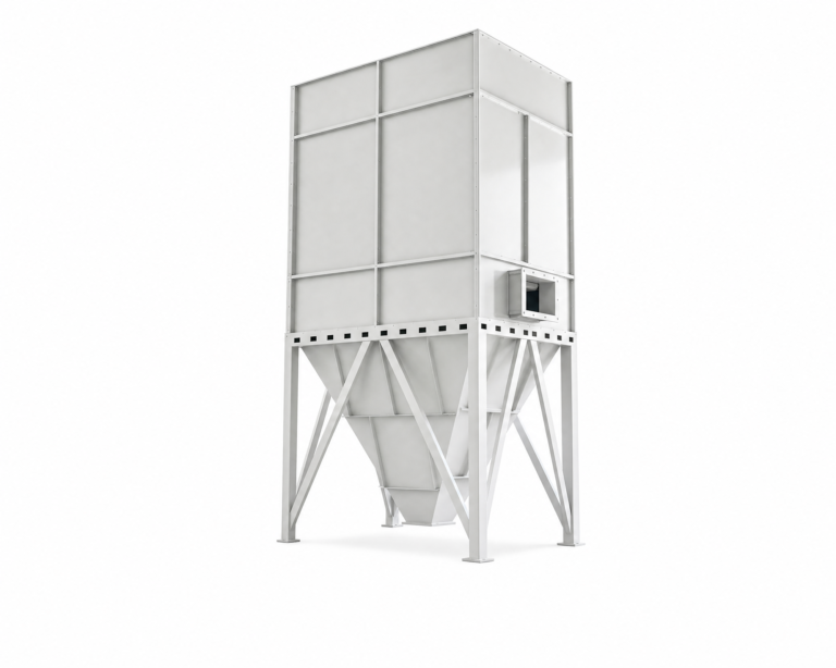
A relação mínima comprimento/largura de 4:1 para tanques retangulares é uma restrição de planejamento que afeta a viabilidade do local antes mesmo de afetar o desempenho. Estações com área ocupada limitada podem constatar que o cumprimento desse requisito geométrico é o verdadeiro obstáculo para um projeto de retenção prolongada, e não a lógica do tratamento. Nesses casos, um torre de sedimentação vertical oferece uma terceira opção: utiliza o volume vertical para atingir o tempo de retenção dentro de uma área ocupada horizontal compacta, e seu projeto se adapta melhor ao tipo de variabilidade de produção que faz com que os decantadores de placas compactos apresentem desempenho inferior. O compromisso passa a recair sobre a dimensão vertical — acesso para manutenção, retirada de lodo em profundidade e restrições de área ocupada versus altura —, mas a resistência a cargas de choque é substancialmente melhorada em relação a uma configuração padrão de decantador de placas.
Para estações em que o controle da dosagem é rigoroso e a retirada de lodo segue um cronograma rígido, projetos compactos são justificáveis. Para estações em que a variabilidade da produção é alta e a disciplina operacional é variável, o layout de retenção prolongada ou vertical oferece a margem de segurança que torna a meta de água reciclada consistentemente alcançável.
Qual sistema de sedimentação é mais adequado para garantir a reutilização estável da água?
A reutilização estável da água não decorre apenas da geometria do tanque — ela resulta da combinação de uma configuração adaptada à variabilidade real de sólidos da estação, dimensionada adequadamente para condições de pico, e não para condições médias, e apoiada por práticas de gestão de lodo que mantêm o cronograma de retirada alinhado com a taxa de acúmulo.
Os decantadores de tubos inclinados podem lidar com concentrações mais elevadas de sólidos em suspensão do que os tanques tradicionais do tipo vertical, o que os torna uma opção adequada para fluxos de efluentes industriais com cargas variáveis — desde que os picos decorrentes da produção não sejam tão acentuados ou frequentes a ponto de os canais entre os tubos não conseguirem se recuperar entre um evento e outro. Trata-se de um critério de planejamento, não de uma certificação de desempenho: a adequação depende da compreensão do perfil de sólidos do processo específico, e não apenas da concentração média de sólidos em suspensão. Para fábricas de cerâmica e pedra com períodos de pico claramente definidos, a questão é se esses picos excedem a janela de recuperação do decantador tubular.
Tanques retangulares de fluxo contínuo dimensionados para um tempo de retenção hidráulica de 90 minutos e complementados com tanques paralelos quando a capacidade de descarga de um único tanque é excedida representam o caminho mais convencional para uma reutilização estável. A disposição de tanques paralelos costuma ser omitida nos projetos iniciais para reduzir o custo de capital, mas é o mecanismo que mantém o desempenho do tratamento durante eventos de pico de vazão. Omitir essa disposição ao dimensionar para o fluxo médio cria uma configuração que funciona corretamente na maior parte do tempo, mas falha nas condições de produção que mais pressionam a meta de qualidade da água reciclada.
| Fator para a reutilização estável da água | Configuração aplicável | O que planejar / verificar |
|---|---|---|
| Tratamento de cargas variáveis/com alto teor de sólidos | Decisonrcdboi lt aete nnduaado | É capaz de lidar com maiores concentrações de sólidos em suspensão do que os modelos verticais tradicionais; adequado para cargas variáveis em aplicações industriais |
| Dimensionamento para vazões de pico | Tanques retangulares de fluxo contínuo | Deve garantir um tempo de retenção hidráulica de 90 minutos; adicionar tanques paralelos quando a vazão exceder a capacidade de um único tanque |
| Equilíbrio na remoção de lodo | Tanques de sedimentação secundária | Lodo sedimentado de retorno (RAS) ou de rejeito (WAS); ajustar as válvulas nas tubulações coletoras para equalizar a remoção e evitar oscilações na qualidade |
A equalização do lodo nas tubulações de coleta — o ajuste das válvulas de drenagem para equilibrar as taxas de remoção nas diferentes seções do tanque — é o detalhe operacional que determina se um tanque dimensionado corretamente fornece água clarificada de qualidade consistente ou se a qualidade se degrada gradualmente até atingir o limite de qualidade na saída. As estações que compreendem isso muitas vezes ainda ignoram a etapa de equalização, pois ela exige atenção durante a produção, e não apenas durante os intervalos de manutenção. A consequência é um acúmulo desigual de lodo, que reduz o volume efetivo de sedimentação em algumas seções, enquanto outras permanecem parcialmente vazias, criando zonas de tempo de retenção reduzido que comprometem a qualidade da água reciclada de maneiras cuja causa é difícil de identificar.
Para obter mais informações sobre como esses sistemas interagem dentro de um contexto mais amplo de reutilização industrial, o Guia abrangente para sistemas de reciclagem de águas residuais aborda considerações de integração que vão além da seleção do tanque, abrangendo decisões relacionadas ao pré-tratamento, ao refinamento e às vias de descarga.
A disciplina fundamental do planejamento para usinas de cerâmica e pedra consiste em rejeitar a conveniência do dimensionamento com base no fluxo médio. Todos os parâmetros — taxa de transbordamento, limite de acúmulo de sedimentos, carga superficial, tempo de retenção — precisam ser calculados com base no pior turno operacional que a planta realmente opera, incluindo ciclos de limpeza em lote e períodos de pico de corte. Um tanque que mantenha sua meta de água reciclada nessas condições terá bom desempenho sob cargas normais; um tanque dimensionado para cargas normais apresentará qualidade imprevisível nas condições que mais importam para a confiabilidade da reutilização.
Antes de definir um projeto, confirme três aspectos: que a meta de qualidade da água reutilizada esteja definida em termos específicos e mensuráveis antes da seleção de qualquer dimensão do tanque; que o perfil de carga de sólidos utilizado para o dimensionamento reflita os picos de produção e não médias suavizadas; e que o sistema de dosagem, o cronograma de retirada de lodo e a geometria do tanque sejam tratados como um sistema integrado, em vez de decisões de projeto independentes. O conflito entre projetos compactos e de retenção prolongada é real, mas é secundário em relação a esses três compromissos — acerte-os primeiro e, em seguida, selecione a geometria que melhor se adapte às restrições do local e à capacidade operacional disponível para gerenciá-la.
Perguntas frequentes
P: O que acontece se a usina ainda não tiver uma meta definida para a qualidade da água reciclada — ainda assim é possível prosseguir com o dimensionamento dos tanques?
R: Não, não de forma significativa. Sem um limite mensurável de sólidos em suspensão para a aplicação de reutilização — seja um circuito de resfriamento, um circuito de água de prensa ou um sistema de corte úmido —, não há um limite de qualidade fixo a partir do qual se possa determinar os parâmetros, o que significa que o tempo de retenção, a taxa de transbordamento e as metas de dosagem serão todos selecionados sem uma restrição determinante. O primeiro passo antes de se definir qualquer dimensão do tanque é definir a meta de reutilização em termos específicos e verificáveis para o processo a jusante que receberá a água. Se a meta for realmente desconhecida, uma abordagem conservadora inicial consiste em identificar o equipamento a jusante mais sensível e usar sua tolerância operacional como limite máximo de qualidade.
P: Após o comissionamento, qual é o primeiro sinal operacional de que o sistema de sedimentação está caminhando para uma falha, antes que uma auditoria completa detecte o problema?
R: Uma tendência lenta de aumento na turbidez da água reciclada durante ou imediatamente após os turnos de pico de produção é o indicador confiável mais precoce. Esse padrão — turbidez que se recupera entre os turnos, mas aumenta gradualmente ao longo de ciclos sucessivos de produção — normalmente aponta para uma das três falhas de integração: acúmulo de lodo invadindo a zona tampão entre os intervalos de retirada, dosagem de coagulante ficando atrás dos picos de sólidos, ou canais de placas compactas ou tubulares começando a acumular partículas finas de cerâmica ou pedra. Acompanhar a turbidez na saída com resolução horária durante os turnos com maior teor de sólidos, em vez de apenas durante os intervalos padrão de monitoramento, torna esse desvio visível com antecedência suficiente para que seja corrigido antes que a geometria ou os cronogramas de dosagem se tornem o fator limitante.
P: Em que ponto a variabilidade da produção de uma planta se torna alta demais para que um decantador compacto de placas ou tubos continue sendo uma opção justificável, mesmo com um controle rigoroso da dosagem?
R: Quando ocorrem eventos com alto teor de sólidos — ciclos de limpeza em lote, purgas para redução de picos ou lavagens no fim do turno — com frequência suficiente para que os canais entre placas ou entre tubos não consigam se desobstruir entre um evento e outro, os decantadores compactos apresentam desempenho consistentemente inferior, independentemente da capacidade de resposta do sistema de dosagem. Um teste útil de planejamento consiste em comparar a frequência e a duração dos picos de sólidos com a capacidade hidráulica de lavagem do decantador entre esses eventos. Se os picos se sobreporem, ou se o intervalo de recuperação for menor do que o tempo necessário para eliminar as partículas finas acumuladas nos canais, o layout compacto gerará um problema de entupimento progressivo, em vez de um problema ocasional. Nesse ponto, a economia de espaço proporcionada pelo projeto compacto é compensada por paradas não planejadas e custos de substituição, e um layout de fluxo horizontal ou retenção vertical torna-se o caminho mais confiável para atingir uma meta estável de reutilização.
P: Vale a pena o investimento em um tanque paralelo de reserva para uma fábrica de cerâmica ou pedra que opera em um único turno e tem horários de produção relativamente previsíveis?
R: Sim, na maioria dos casos, mesmo para fábricas que operam em um único turno. A justificativa não é a produtividade média diária — mas sim o fato de que os ciclos de limpeza em lote e os períodos de pico de corte criam condições instantâneas de vazão e de sólidos que podem exceder o limite de carga superficial de um único tanque, independentemente de quão previsível seja o cronograma de turnos. Um tanque de reserva oferece a capacidade de manter o desempenho do tratamento durante esses picos, sem forçar uma escolha entre reduzir a produção e aceitar uma qualidade degradada da água reciclada. Para instalações em que os picos são curtos e pouco frequentes, o tanque de reserva fica o tempo todo ocioso, mas seu valor se destaca justamente durante as condições de produção que mais sobrecarregam a meta da água de reciclagem. Dimensionar o tanque primário para lidar com o fluxo instantâneo de pico e omitir a unidade de reserva só funciona se o fluxo instantâneo de pico nunca exceder o limite de carga superficial de um único tanque — uma condição que os cálculos de fluxo médio não podem confirmar.
P: Como a frequência de retirada de lodo deve ser recalculada se a estação passar de operações com um único produto para operações com vários produtos, com características de sólidos diferentes?
R: O cronograma de retirada precisa ser redefinido com base no novo perfil de carga de sólidos para o pior cenário possível, em vez de ser ajustado gradualmente a partir do cronograma existente. Produtos diferentes — cerâmica esmaltada versus não esmaltada, diferentes tipos de pedra — geram distribuições de granulometria e velocidades de sedimentação distintas, o que altera tanto a taxa de acúmulo na zona de lodo quanto a composição química da dosagem necessária para agregar partículas finas acima do limiar de velocidade do fluxo ascendente. O limite máximo de acumulação de sedimentos de 25% continua sendo a restrição determinante, mas a taxa na qual esse limite é atingido variará entre os tipos de produto. Uma abordagem prática consiste em medir a profundidade do lodo ao final do turno com maior teor de sólidos para cada novo tipo de produto durante as duas primeiras semanas de operação com múltiplos produtos, usar essas medições para definir um intervalo de retirada específico para cada produto e, em seguida, programar a retirada com base no tipo de produto que gerar a taxa de acumulação mais rápida durante qualquer semana de produção.